
SZTUKA
Piękno i dobre samopoczucie
RZEMIOSŁO
KULTURA I HISTORIA
ROZRYWKA
ŚRODOWISKO
JEDZENIE I NAPOJE
INŻYNIERIA ODWROTNA
NAUKI
LEKKOATLETYKA
TECHNOLOGIA
URZĄDZENIA DO NOSZENIA
Metal Band Saw: Horizontal Saw on a Welded Steel Frame
Martin

Autor

Martin

23. październik 2026NO
9
0
0
0
0

Metal Band Saw: Horizontal Saw on a Welded Steel Frame

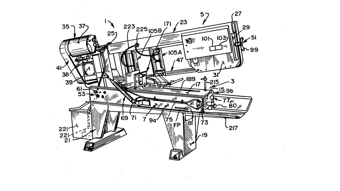
Curtis Eccardt's horizontal power band saw (Emerson Electric, US 4,364,294, 1982), built from welded steel channel and tube instead of iron castings to cut its cost. The saw head swings down on trunnions over the bed; a hydraulic cylinder with a valve sets how fast it feeds, a spring counterbalances it, and a spring tensioner shows the blade tension on a scale. Two guides with rollers twist the blade's lower run 90° so its teeth face down into the work, and carbide inserts hold it there. The patent gives no sizes, speeds or ratings; the welder and wrenches are ours. The picture: the patent's Fig. 1.
Zaawansowany
4 days

Instrukcje

1

Weld the bed

Stand two steel channels (9a, 9b) parallel, webs upright and flanges facing in, and weld gussets (15) between their webs. Bolt a bed plate (17) across the top flanges as the work surface. Ours: MIG welder, drill press for the bolt holes.

Materiały do tego kroku:

Ceownik stalowyCeownik stalowy2 sztuk
Blacha gruba ze stali niskowęglowejBlacha gruba ze stali niskowęglowej1 sztuka
Śruba z łbem sześciokątnym - klasa 8.8Śruba z łbem sześciokątnym - klasa 8.81 sztuka

Potrzebne narzędzia:

Spawarka MIGSpawarka MIG
Wiertarka stołowaWiertarka stołowa
Klucz nastawnyKlucz nastawny
2

Weld and bolt on the legs

Weld formed sheet-steel legs onto horizontal floor members to make front and rear leg weldments (19, 21), and bolt them under the bed.

Materiały do tego kroku:

Blacha stalowaBlacha stalowa1 sztuka
Rura stalowa konstrukcyjnaRura stalowa konstrukcyjna1 sztuka
Śruba z łbem sześciokątnym - klasa 8.8Śruba z łbem sześciokątnym - klasa 8.81 sztuka

Potrzebne narzędzia:

Spawarka MIGSpawarka MIG
Klucz nastawnyKlucz nastawny
3

Weld the head

Weld a head post (25) of square or rectangular steel tube square to a head beam (27) of rectangular tube. Weld a bracket leg (29) down from the beam's outer end, and fix support plates at both ends (31, 33).

Materiały do tego kroku:

Rura stalowa konstrukcyjnaRura stalowa konstrukcyjna1 sztuka
Blacha gruba ze stali niskowęglowejBlacha gruba ze stali niskowęglowej1 sztuka

Potrzebne narzędzia:

Spawarka MIGSpawarka MIG
4

Fit the trunnions and align the pivot

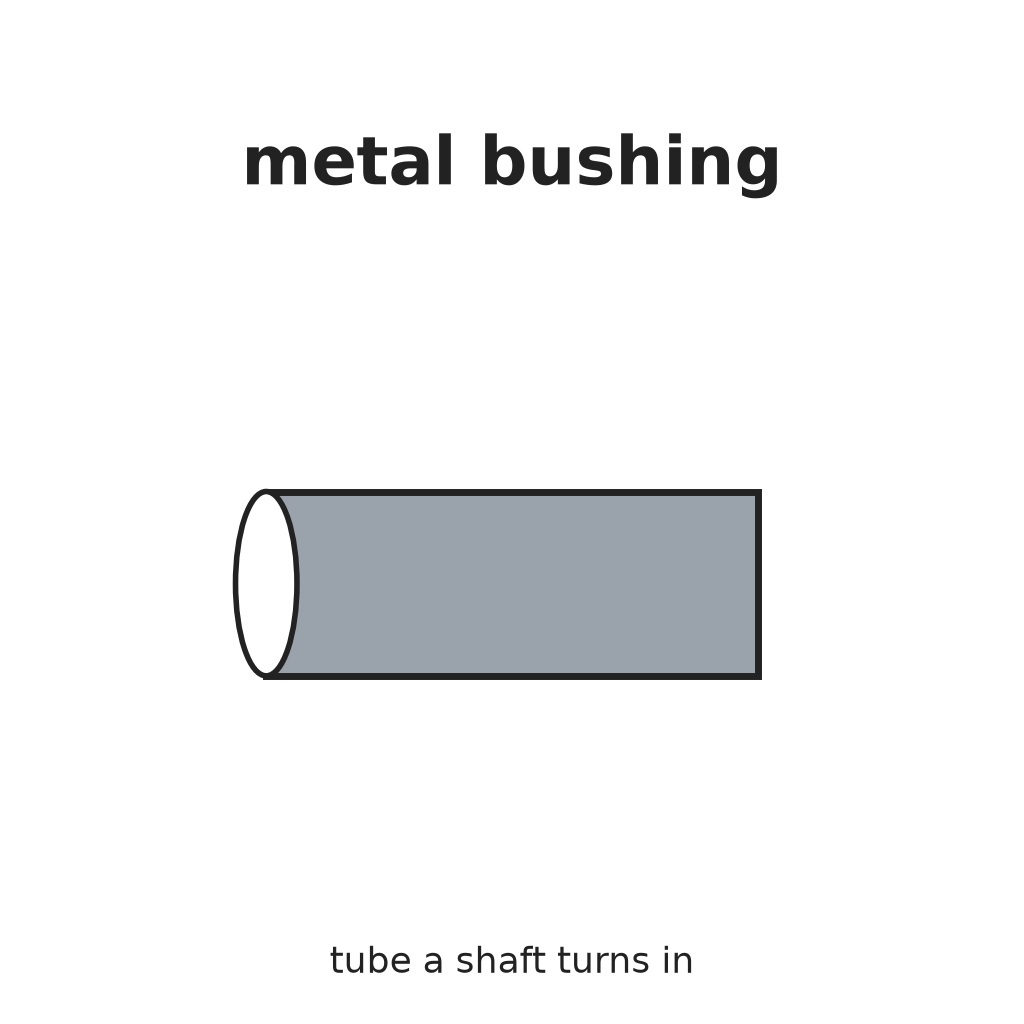
Fix a shaft through the head post with its ends out as trunnions (55a, 55b), in bushings in two bearing blocks (59a, 59b) bolted inside the channel webs. Each block has one close-fit bolt hole and three oversize ones: shift the blocks until the pivot is parallel to the bed plate, then torque the bolts. A set screw (67) takes out end play.

Materiały do tego kroku:

Wał stalowyWał stalowy1 sztuka
Metalowa tulejaMetalowa tuleja2 sztuk
Oprawa łożyskaOprawa łożyska2 sztuk
Śruba z łbem sześciokątnym - klasa 8.8Śruba z łbem sześciokątnym - klasa 8.88 sztuk
Wkręt dociskowy z końcówką wklęsłąWkręt dociskowy z końcówką wklęsłą1 sztuka

Potrzebne narzędzia:

Wiertarka stołowaWiertarka stołowa
Klucz dynamometrycznyKlucz dynamometryczny
5

Mount motor, belt drive and gearbox

Mount the electric motor (37) on a plate (38) pivoted on the head beam, and couple it by a multi-speed belt and pulleys (41) to a gearbox (39). Fit the drive wheel (43) on the gearbox output shaft.

Materiały do tego kroku:

Silnik elektrycznySilnik elektryczny1 sztuka
Blacha gruba ze stali niskowęglowejBlacha gruba ze stali niskowęglowej1 sztuka
Pas napędowyPas napędowy1 sztuka
KrążekKrążek1 sztuka
Przekładnia zębataPrzekładnia zębata1 sztuka
Koło piły taśmowejKoło piły taśmowej1 sztuka

Potrzebne narzędzia:

Klucz nastawnyKlucz nastawny
6

Build the idler tensioner

Weld an idler yoke (87) of rolled steel plate, pivot it on the head beam with a pin (89), and cantilever the idler axle from it with the idler wheel (45) on bearings (85). A threaded rod (91) pulls the yoke through a coil spring (93) held between compression plates and a U-bolt (97); a knob (99) turns the rod. An indicator (101) on the spring reads the tension on a scale (103).

Materiały do tego kroku:

Blacha gruba ze stali niskowęglowejBlacha gruba ze stali niskowęglowej1 sztuka
Kołek stalowy wciskanyKołek stalowy wciskany1 sztuka
Wał stalowyWał stalowy1 sztuka
Koło piły taśmowejKoło piły taśmowej1 sztuka
Łożysko kulkoweŁożysko kulkowe1 sztuka
Pręt gwintowanyPręt gwintowany1 sztuka
Coil SpringCoil Spring1 sztuka
Strzemię w kształcie litery UStrzemię w kształcie litery U1 sztuka
Gałka sterującaGałka sterująca1 sztuka

Potrzebne narzędzia:

Spawarka MIGSpawarka MIG
Klucz nastawnyKlucz nastawny
7

Build the two blade guides

In each guide channel (111) mount two guide rollers (115a, 115b) on ball bearings on eccentric bushings, one fixed and one adjusted to the blade thickness. Add a carbide thrust insert (133) on the blade's back edge and two carbide side inserts (137a fixed, 137b on a sprung swing bracket set by a bolt and knob). Clamp the guides on two bar tracks (107).

Materiały do tego kroku:

Rolka prowadzącaRolka prowadząca4 sztuk
Łożysko kulkoweŁożysko kulkowe4 sztuk
Tuleja mimośrodowaTuleja mimośrodowa4 sztuk
Płytka z węglika spiekanegoPłytka z węglika spiekanego6 sztuk
Coil SpringCoil Spring2 sztuk
Gałka sterującaGałka sterująca2 sztuk
Rura stalowa konstrukcyjnaRura stalowa konstrukcyjna1 sztuka

Potrzebne narzędzia:

Klucz nastawnyKlucz nastawny
8

Fit the blade and set the tension

By hand, run the endless blade (47) round the drive and idler wheels and through both guides; the rollers twist its lower run about 90° so the teeth face down. Turn the tension knob until the scale shows the tension you want.

Materiały do tego kroku:

Brzeszczot do pilarki taśmowejBrzeszczot do pilarki taśmowej1 sztuka
9

Fit the feed cylinder and counterbalance

Connect a hydraulic cylinder (71) between bed channel and head post above the trunnions, filled with oil and piped through tubing (75) to a control valve (73): the valve sets the feed rate and, closed, holds the head. Fit a coil spring (78) on a threaded linkage (79) between an end gusset and the head post below the trunnions, adjusted by a knob (80), to counterbalance the head.

Materiały do tego kroku:

Siłownik hydraulicznySiłownik hydrauliczny1 sztuka
Olej hydraulicznyOlej hydrauliczny1 batch
Rurka hydraulicznaRurka hydrauliczna1 sztuka
Zawór regulacji przepływuZawór regulacji przepływu1 sztuka
Coil SpringCoil Spring1 sztuka
Pręt gwintowanyPręt gwintowany1 sztuka
Gałka sterującaGałka sterująca1 sztuka

Potrzebne narzędzia:

Klucz nastawnyKlucz nastawny
10

Bolt on the vice

Bolt the quick-acting vice to the bed plate to clamp the work square under the blade.

Materiały do tego kroku:

Imadło maszynoweImadło maszynowe1 sztuka
Śruba z łbem sześciokątnym - klasa 8.8Śruba z łbem sześciokątnym - klasa 8.81 sztuka

Potrzebne narzędzia:

Klucz nastawnyKlucz nastawny

Materiały

29

Wymagane narzędzia

4

Według tego planu powstaje

CC0 Domena publiczna

Ten plan jest udostępniany na licencji CC0. Możesz go swobodnie kopiować, modyfikować, rozpowszechniać i wykorzystywać do dowolnych celów, bez konieczności uzyskiwania zgody.

Wesprzyj Makera kupując produkty przez jego plan, za co zarabia Prowizja Makera ustalony przez sprzedawców, lub stwórz nową iterację tego planu i dołącz go jako połączenie w swoim własnym planie, aby dzielić się przychodami.

Dyskusja

(0)

Zaloguj się aby dołączyć do dyskusji

Ładowanie komentarzy...