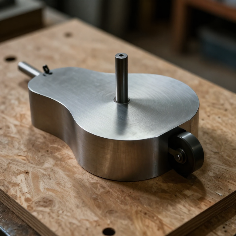


Plate Cam and Follower
Instrukcje
Draw the displacement diagram FIRST
Draw the displacement diagram FIRST
Decide the motion on paper before touching metal. This is the design step.
- Rule a chart 360 mm long: crank angle 0-360 degrees across, follower lift 0-25 mm up.
- Plot your motion: rise 25 mm over 0-90 degrees, dwell to 180, fall to zero by 270, dwell to 360.
- Round off the corners at each transition over about 15 degrees.
- Read off the required lift every 15 degrees and tabulate all 24 values.
Why the corners must be rounded. A sharp corner on the displacement diagram means instantaneous change of velocity — infinite acceleration, which in practice means the follower hammers the cam and bounces off it. Smoothing the transitions is not cosmetic; it is what makes the cam survivable at speed. Real cams use defined curves such as cycloidal or harmonic motion for exactly this reason.
Your 24 tabulated values ARE the cam. Everything after this is transferring them accurately to metal.Materiały do tego kroku:
 Sklejka z brzozy bałtyckiej1 opakowanie
Potrzebne narzędzia:
 Kątownik nastawny
 Suwmiarka cyfrowa 6 cali
Convert the diagram to a polar profile
Convert the diagram to a polar profile
Twenty-four radial measurements, transferred one at a time.
- Scribe a 60 mm radius base circle on 6 mm aluminium flat bar and mark 24 radial lines at 15 degree intervals.
- Along each radial, measure OUT from the base circle by that angle's tabulated lift.
- Centre-punch each of the 24 points.
- Join them in a smooth curve — a thin steel rule sprung around the punch marks gives a fair curve.
- Drill the centre 8.0 mm for a 608 bearing.
Modern build spec (derived). A 60 mm base circle with 25 mm lift keeps the pressure angle reasonable everywhere. Too small a base circle for a given lift makes the profile steep, and the follower is then pushed sideways rather than along its axis — it jams in its guide. Base circle is a real design parameter, not an arbitrary starting size.
Fair the curve by eye through all 24 points rather than joining them with straight segments. Any flat spot you leave becomes a jolt in the output.Materiały do tego kroku:
 Płaskownik aluminiowy1 sztuka
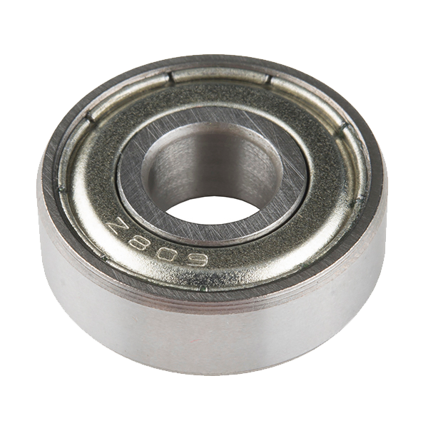 Ball Bearing - Non-Flanged (8mm Bore, 22mm OD)1 sztuka
Potrzebne narzędzia:
 PunktakSuwmiarka cyfrowa 6 caliKątownik nastawny
 Wiertarko-wkrętarka akumulatorowa
 Zestaw wierteł
Cut and fair the profile
Cut and fair the profile
Saw outside the line, then file to it. The filing is where the accuracy comes from.
- Rough out with the jigsaw, staying 1 mm proud of the scribed curve everywhere.
- File down to the line, working around the profile repeatedly rather than finishing one area at a time.
- Check as you go: measure from centre to edge at each 15 degree radial and compare with your table.
- Deburr both faces.
Potrzebne narzędzia:
 Wyrzynarka
 Zestaw pilników
 Imadło warsztatoweSuwmiarka cyfrowa 6 cali
Build the follower and hold it against the cam
Build the follower and hold it against the cam
A cam can only push. Something else must supply the return.
- Cut a baseplate 300 × 220 mm from 18 mm ply and mount the cam through its bearing with an M5 × 40 socket head cap screw, M5 flat washer × 2, M5 hex nut × 1.
- Make a follower rod from 6 mm aluminium flat bar, running in two guide blocks fixed with M4 × 25 socket head cap screws × 4, M4 flat washers × 8, M4 nylon insert lock nuts × 4.
- Fit a second 608 bearing at the follower's lower end as a ROLLER follower.
- Fit a compression spring above the follower to hold the roller against the cam at all times.
What the patent-era machines used: a flat or knife-edge follower in a bronze guide, oiled. Modern build spec (derived): a 608 as a roller follower — it converts sliding to rolling exactly as on the Scotch yoke's pin, and it is why a modern roller-follower camshaft outlasts a flat-tappet one.
The spring must be strong enough that the roller never leaves the cam on the falling flank. If it does, the follower floats and lands with a hammer blow — the same valve float that limits an engine's safe revolutions.Materiały do tego kroku:
Sklejka z brzozy bałtyckiej1 arkuszPłaskownik aluminiowy1 sztukaBall Bearing - Non-Flanged (8mm Bore, 22mm OD)1 sztuka Zestaw sprężyn naciskowych1 zestaw
 Śruba z łbem walcowym na imbus4 sztuk
 Podkładka płaska8 sztuk
 Nakrętka samohamowna z wkładką nylonową4 sztukPodkładka płaska2 sztuk
 Nakrętka sześciokątna1 sztuka
Potrzebne narzędzia:
Wiertarko-wkrętarka akumulatorowaZestaw wierteł Zestaw pogłębiaczy stożkowych
 Zestaw kluczy imbusowych
 Piłka włosowaKątownik nastawny
Verify against your own drawing, and history
Verify against your own drawing, and history
The cam's whole promise is that it does what you drew. Check it.
- Fit a protractor disc to the cam shaft.
- Turn in 15 degree steps and measure the follower's height with the caliper at each.
- Plot your measurements over the original displacement diagram.
- Where they diverge, mark the corresponding sector on the cam and file it.
History. Cams are old — they appear in Hellenistic automata and in medieval trip-hammer and fulling mills, where pegs on a rotating shaft lift a hammer and drop it. The systematic design method used here, going from displacement diagram to profile, belongs to the machine-tool era, and it is what made the automatic screw machine possible: a bank of cams on one shaft sequencing every tool in the machine, which is mechanical programming in the most literal sense.
Where it sits among its siblings: the Geneva drive gives intermittent rotation with one fixed motion pattern; the Scotch yoke gives a sinusoid; a linkage gives whatever its bar lengths dictate. Only the cam gives ARBITRARY motion, including dwells. That freedom costs you a profile that must be accurately made, cannot be adjusted afterwards, and wears in a way that changes the motion — which is why cams are found where the same motion repeats millions of times, and linkages where it does not.
Potrzebne narzędzia:
Suwmiarka cyfrowa 6 caliZestaw pilnikówMateriały
10- 1 opakowanieZastępnik
- 1 sztukaZastępnik
- Ball Bearing - Non-Flanged (8mm Bore, 22mm OD)10% prowizji1 sztuka$1.26
- 1 arkuszZastępnik
- 1 zestawZastępnik
- Zastępnik
- 8 sztukZastępnik
- Zastępnik
- 2 sztukZastępnik
- 1 sztukaZastępnik
Wymagane narzędzia
11- Zastępnik
- Zastępnik
- Zastępnik
- 1 vendor sell this, none ship to you yetZastępnik
- Zastępnik
- 1 vendor sell this, none ship to you yetZastępnik
- Zastępnik
- Zastępnik
- Zastępnik
- Zastępnik
- Zastępnik
Powiązane blueprinty
Te blueprinty dzielą się wiedzą — technikami, materiałami lub zasadami

CC0 Domena publiczna
Ten plan jest udostępniany na licencji CC0. Możesz go swobodnie kopiować, modyfikować, rozpowszechniać i wykorzystywać do dowolnych celów, bez konieczności uzyskiwania zgody.
Wesprzyj Makera kupując produkty przez jego plan, za co zarabia Prowizja Makera ustalony przez sprzedawców, lub stwórz nową iterację tego planu i dołącz go jako połączenie w swoim własnym planie, aby dzielić się przychodami.