Współpraca
SZTUKA
Piękno i dobre samopoczucie
RZEMIOSŁO
KULTURA I HISTORIA
ROZRYWKA
ŚRODOWISKO
JEDZENIE I NAPOJE
INŻYNIERIA ODWROTNA
NAUKI
LEKKOATLETYKA
TECHNOLOGIA
URZĄDZENIA DO NOSZENIA
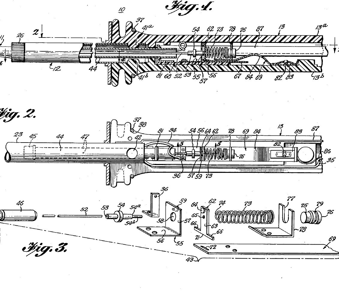


Soldering Iron: Temperature Controlled by a Curie-Point Tip and a Magnet Switch (Weller, US 3,188,448, 1965)
A soldering iron that holds its own tip temperature. At the back of the copper tip sits a slug of nickel-iron alloy that stops being magnetic above a set temperature (its Curie point). A small Alnico magnet behind it is pulled forward while the slug is cool, closing a switch that feeds the heater; once the tip is hot the slug lets go, a steel bushing pulls the magnet back and the switch opens. Swap tips to choose 600, 700 or 800 °F.
Result: a 55-watt temperature-controlled iron idling near 700 °F instead of running ever hotter.
Source: C. E. Weller, US 3,188,448 (1965). Unknown: the plating baths, the heater wire and insulation, most sizes. Picture: the patent drawing.
Zaawansowany
Unknown
Instrukcje
1
1
Make the tip and control slug
Make the tip and control slug
Turn the tip from tellurium copper: a cylindrical body, a taper and a chisel end (any shape suits the work). Plate it first with iron, which keeps the copper out of the molten solder, then with nickel, which shuts out the air. Bore its rear end and fit tightly into it the shank of a slug of thermomagnetic nickel-iron alloy, such as 48 % nickel, 3 % molybdenum and the rest iron, or about 43 % nickel and the rest iron. The alloy sets the control point: make tips for 600, 700 and 800 °F. Not given: the plating baths, sizes.
Materiały do tego kroku:
 Pręt z miedzi tellurowej1 tip
 Termomagnetyczny stop niklowo-żelazny1 control slug
Potrzebne narzędzia:
 Tokarka do metalu
 Zestaw do galwanizacji
 Nieznane wymiary
2
2
Wind the heater barrel
Wind the heater barrel
Make the barrel of two stainless steel tubes: an inner spool the tip slides into snugly, and an outer cover tube joined to it at the front, with a thread and screw cap to hold the tip. In the space between them wind the heater from one length of resistance wire: an inner layer, then an outer layer wound the opposite way so their fields cancel, with insulating sheet inside, between and outside the layers. Silver-solder heat-resistant leads to its ends. Ours: nichrome wire. Not given: the insulating sheet, the turns.
Materiały do tego kroku:
 Rura ze stali nierdzewnej2 spool and cover tube
 Drut oporowy nichromowy1 heater
 Nieznany materiał izolacyjny1 three sheet layers
 Nieznany metal1 leads
 Lut srebrny1 as needed
Potrzebne narzędzia:
 Palnik propanowyTokarka do metalu
3
3
Build the magnet switch
Build the magnet switch
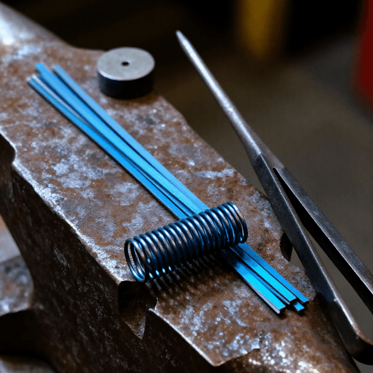
In a stainless steel sleeve about 2.4 in long, close the front with a non-magnetic thermal bushing. Behind it slides a cylindrical Alnico V magnet, then a non-magnetic spacer about 0.032 in thick, then a cold-drawn steel bushing about 0.50 in long held by dents in the sleeve; the magnet's stroke is about 0.015 in. A push rod runs from the magnet through the bushing to an insulator. On a melamine plate, hinge a moving contact between a thin conducting strip and a holding strip, facing a flexible contact; a spring of fourteen coils of 0.010 in music wire, 0.210 in across, presses the moving contact toward the flexible one. Rivet the spring bracket to the holding strip. Not given: the contact metals.
Materiały do tego kroku:
Rura ze stali nierdzewnej1 sleeve Magnes alnico1 sztuka
 Pręt ze stali niskowęglowej1 magnetic bushing, push rodNieznany metal1 thermal bushing, spacer, contacts, strips, brackets
 Nieznany materiał1 insulator
 Płyta melaminowa1 base plate
 Drut sprężynowy1 0.010 in music wire spring
Potrzebne narzędzia:
Tokarka do metalu Zestaw nitowniczy
 Szczypce okrągłe
4
4
Assemble the handle and use
Assemble the handle and use
Mould the handle in two plastic halves with a socket at the front whose bosses lock the cover tube. Lay in the switch unit, held only by the bowed tail of its holding strip on an anchor pin with a speed nut, so it floats and its thermal bushing presses on the tip's slug. Wire the heater, the switch and a ground lead from the cover tube to the cord. Rivet the halves near the butt and fit a split ring near the front. In use, below the control point the slug pulls the magnet forward and the spring closes the contacts; above it the steel bushing pulls the magnet back and the push rod opens them. At idle the heater runs only about 30 to 40 % of the time. Not given: the plastic.
Materiały do tego kroku:
Nieznany materiał1 handle halvesNieznany metal1 rivet, split ring, speed nut Przewód giętki z wtyczką1 sztuka
Potrzebne narzędzia:
 WtryskarkaZestaw nitowniczy
Materiały
13- Zastępnik
- 1 control slugZastępnik
- 1 sleeveZastępnik
- 1 heaterZastępnik
- 1 three sheet layersZastępnik
- 1 rivet, split ring, speed nutZastępnik
- 1 as neededZastępnik
- 1 sztukaZastępnik
- 1 magnetic bushing, push rodZastępnik
- 1 handle halvesZastępnik
- 1 base plateZastępnik
- 1 0.010 in music wire springZastępnik
- 1 sztukaZastępnik
Wymagane narzędzia
7- Zastępnik
- Zastępnik
- Zastępnik
- Zastępnik
- Zastępnik
- Zastępnik
- Zastępnik
Materiały z połączonych planów

Według tego planu powstaje

CC0 Domena publiczna
Ten plan jest udostępniany na licencji CC0. Możesz go swobodnie kopiować, modyfikować, rozpowszechniać i wykorzystywać do dowolnych celów, bez konieczności uzyskiwania zgody.
Wesprzyj Makera kupując produkty przez jego plan, za co zarabia Prowizja Makera ustalony przez sprzedawców, lub stwórz nową iterację tego planu i dołącz go jako połączenie w swoim własnym planie, aby dzielić się przychodami.