SZTUKA
Piękno i dobre samopoczucie
RZEMIOSŁO
KULTURA I HISTORIA
ROZRYWKA
ŚRODOWISKO
JEDZENIE I NAPOJE
INŻYNIERIA ODWROTNA
NAUKI
LEKKOATLETYKA
TECHNOLOGIA
URZĄDZENIA DO NOSZENIA



The Ferguson Hitch: A Virtual Pivot Ahead of the Axle
A plough pinned to a tractor's drawbar behind the rear axle does two bad things: on a hillside it slides downhill with the tractor's tail, and when the driver steers away from a crop row it swings the wrong way first, into the crop.
Harry Ferguson of Belfast replaced the pin with two links whose rear ends are wider apart than their front ends. Produced forward, their centre lines meet at a point ahead of the real joints, and the implement swings as if hitched there — so it follows the steering. US 1,916,945, filed 6 June 1929 and granted 4 July 1933, adds a lower link so the implement keeps vertical freedom and an effective line of draft that holds it in the ground, as in his earlier US 1,464,130.
This rung finds the virtual centre from the link geometry, shows why it follows the steering, works out how the line of draft loads the rear wheels, and builds a plan-view model to prove it.
Średniozaawansowany
About 3 hours
Instrukcje
1
1
Virtual centre, steering response and line of draft
Virtual centre, steering response and line of draft
Wczytywanie notatnika Jupyter…
2
2
Build a plan-view hitch model
Build a plan-view hitch model
Cut a tractor outline from plywood about 300 mm long and mark its rear axle line. Screw two pivots behind the axle, 50 mm apart. Cut two balsa links 200 mm long, and a balsa 'implement' bar with two pivots 90 mm apart. Pin the links between them with machine screws so they converge towards the tractor, as in Ferguson's Fig. 2.
Lay a steel rule along each link and draw its line forward on the tractor board: the lines cross ahead of the axle. That is the virtual centre.
Now pin a second implement to a single screw 100 mm behind the axle. Pull the tractor slowly along a paper strip marked as a crop row and steer it left by turning it about a point on its axle line. Watch each implement's tip: the single-pin one swings right before it follows; the linked one moves left at once. Measure the swing with a protractor at each position.
Materiały do tego kroku:
 Płyta sklejkowa1 sztuka
 Płytka z drewna balsa1 sztuka
 Śruby maszynowe8 sztuk
Potrzebne narzędzia:
 Linijka
 Kątomierz
 Wiertarko-wkrętarka akumulatorowa
 Zestaw wierteł
 Marker permanentny
3
3
Read the second sheet: the lower link
Read the second sheet: the lower link
Sheet 2 shows the modification of Figs. 3 and 4. The two links (4, 5) now run from the tractor to cranks on a cross shaft 8 carried high on a triangular frame on the implement, and a **lower link 6** is universally jointed between the implement frame and the rear of the tractor.
The patent: "This form of upper and lower linkage permits the implement to have vertical and lateral freedom while giving a virtual swinging centre forward of the actual connection and an effective line of draft from a point other than the said actual connection." Turning the cross shaft with lever 9 changes the angle of the implement to the tractor, to set the furrow width or keep a cultivator on its rows.
Swap the roles — two lower links and one upper — and add a hydraulic ram to lift them, and this becomes the three-point linkage Ferguson later put into production.

4
4
The hydraulic lift that came next
The hydraulic lift that came next
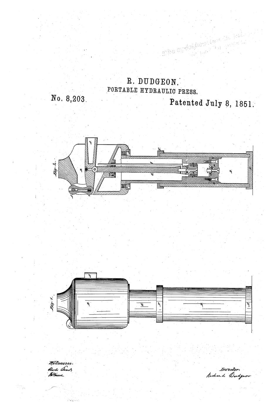
Ferguson's production system lifted the links with a hydraulic ram and used the pull of the implement to control it. The embedded blueprint shows how a hand pump and a ram multiply force — the same principle.
5
5
History and context
History and context
**Harry Ferguson** filed **US 1,916,945**, *Tractor Drawn Agricultural Implement*, on 6 June 1929 (British priority 3 July 1928); it was granted 4 July 1933. It builds on his **US 1,464,130** of 7 August 1923.
The Ferguson-Brown tractor of 1936 carried a three-point linkage lifted by hydraulics, and from 1939 the Ford 9N tractor was built with the Ferguson system. Three-point linkages are now standardised in sizes, so implements fit tractors of every make.
**Honest limits.** The virtual centre helps the implement follow the steering, but a mounted implement also moves the tractor's balance: heavy rear-mounted tools lift weight off the front axle and can make steering light. The simple statics in the notebook ignore wheel slip and soil variation, which real draft control has to cope with.
Materiały
3- 1 sztukaZastępnik
- 1 sztukaZastępnik
- 8 sztukZastępnik
Wymagane narzędzia
5- Zastępnik
- Zastępnik
- 1 vendor sell this, none ship to you yetZastępnik
- Zastępnik
- Zastępnik
Powiązane blueprinty
Te blueprinty dzielą się wiedzą — technikami, materiałami lub zasadami

CC0 Domena publiczna
Ten plan jest udostępniany na licencji CC0. Możesz go swobodnie kopiować, modyfikować, rozpowszechniać i wykorzystywać do dowolnych celów, bez konieczności uzyskiwania zgody.
Wesprzyj Makera kupując produkty przez jego plan, za co zarabia Prowizja Makera ustalony przez sprzedawców, lub stwórz nową iterację tego planu i dołącz go jako połączenie w swoim własnym planie, aby dzielić się przychodami.