Сотрудничество
ИСКУССТВО
КРАСОТА И ЗДОРОВЬЕ
РЕМЕСЛО
КУЛЬТУРА И ИСТОРИЯ
РАЗВЛЕЧЕНИЯ
ЭКОЛОГИЯ
ЕДА И НАПИТКИ
ОБРАТНАЯ ИНЖЕНЕРИЯ
НАУКИ
СПОРТ
ТЕХНОЛОГИИ
НОСИМЫЕ УСТРОЙСТВА
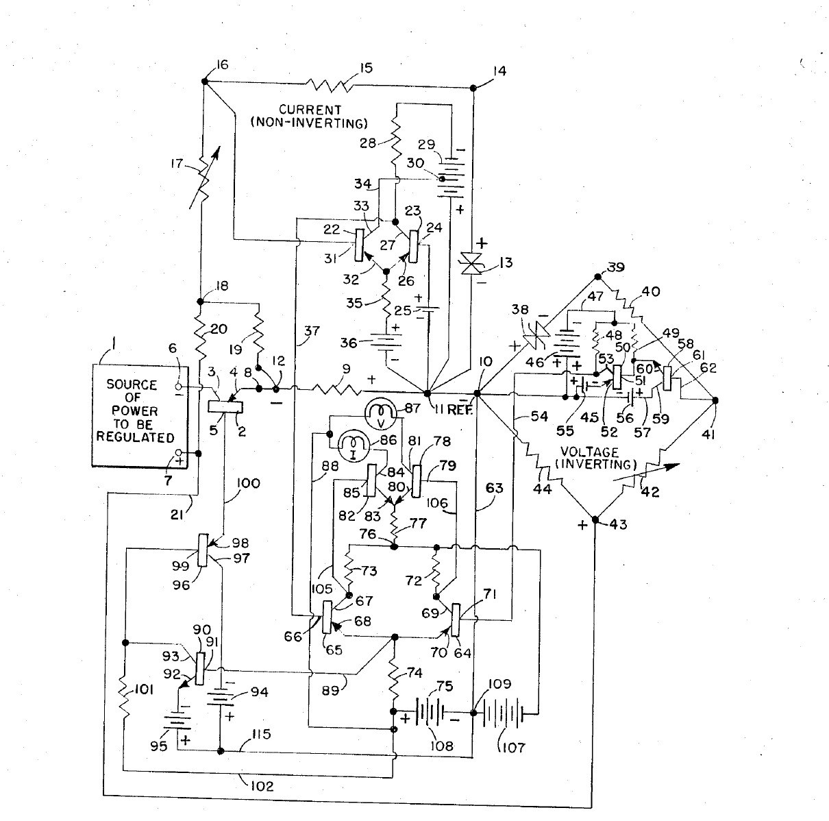


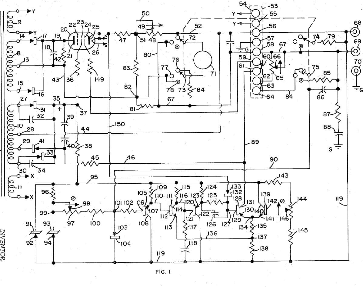
Adjustable Bench Power Supply: Constant Voltage / Constant Current with Cross-Over Lamps (Gately, Forbro, US 3,303,411, 1967)
An all-transistor bench supply with two knobs: one sets the voltage, the other the current. It holds the set voltage until the load tries to draw more than the set current, then switches at once to holding the current, and back again, with no in-between state. Two lamps show which mode is in control.
Result: an adjustable constant-voltage / constant-current DC supply with mode lamps.
Source: J. R. Gately (Forbro Design), US 3,303,411 (1967). Unknown: all component values and ratings. Builds on the same inventor's 1966 current-limited supply. Picture: the patent drawing.
Продвинутый
Unknown
Инструкции
1
1
Build the raw supplies
Build the raw supplies
In a case, wire the cord through a switch and fuse to two power transformers, each with rectifiers and a filter: one gives the main power to be regulated, the other the bias supplies, held steady by Zener diodes. Not given: the voltages. Ours: the case, switch and fuse.
Материалы для этого шага:
 Алюминиевый корпус1 штука
 Гибкий шнур с вилкой1 штука
 Тумблер1 штука
 Плавкий предохранитель1 штука
 Понижающий трансформатор2 штук
 Диод6 rectifiers
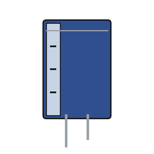 Электролитический конденсатор3 filters
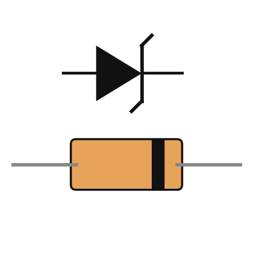 Стабилитрон2 bias
Необходимые инструменты:
 Ручная дрель
 Набор отвёрток
2
2
Fit the pass transistor and current bridge
Fit the pass transistor and current bridge
Put a power transistor on a heat sink in series with the output: collector to the negative supply, emitter through a current-sensing resistor to the negative output terminal. Make the current bridge from the sensing resistor, a reference Zener, a reference resistor and the adjustable current-control resistor: the output current is proportional to its setting. A small trimming resistor sets the maximum current. Not given: the values.
Материалы для этого шага:
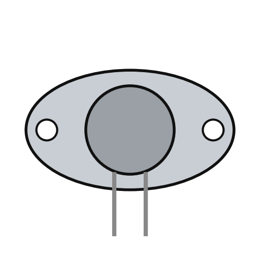 Мощный транзистор1 series pass
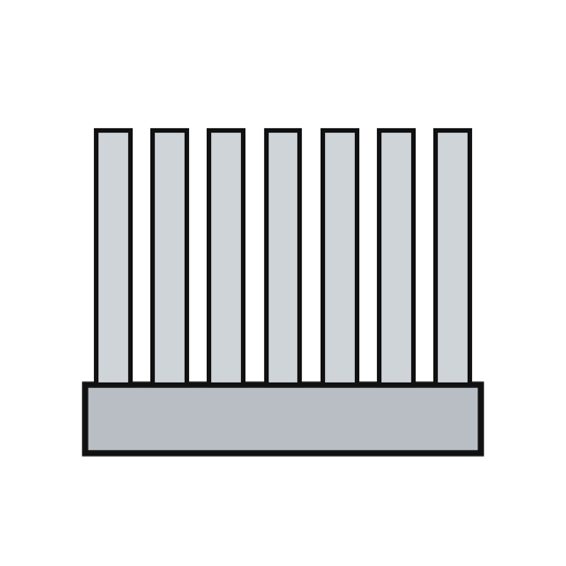 Радиатор1 штукаСтабилитрон1 current reference
 Реостат1 current control
 Сопротивление1 sensing, reference, trim set
 Клемма-барашек2 output + and -
Необходимые инструменты:
 Паяльник
3
3
Build the voltage bridge
Build the voltage bridge
Make the voltage bridge from a reference Zener, a reference resistor, the adjustable voltage-control resistor and the load itself across the output. A small trimming resistor sets the maximum voltage. Add two resistors that feed the current bridge enough extra to cover the voltage bridge's own current and any voltmeter across the output, so low currents are still held exactly.
Материалы для этого шага:
Стабилитрон1 voltage referenceРеостат1 voltage controlСопротивление1 reference, trim, compensation setНеобходимые инструменты:
Паяльник4
4
Build the amplifiers and cross-over
Build the amplifiers and cross-over
Give each bridge an error amplifier. Feed the two amplified errors to the bases of a pair of transistors sharing one emitter resistor: whichever base is the more negative takes control and cuts the other off, so the supply is always cleanly in voltage mode or current mode. Amplify the shared emitter signal through two more transistors to drive the pass transistor's base. Add an emitter-follower clamp on the bias line. Not given: the transistor types.
Материалы для этого шага:
 Печатная плата1 штука
 Набор транзисторов1 error amplifiers, cross-over pair, drivers, clampСопротивление1 набор
 Потенциометр1 clamp divider
 Проволочный припой1 as needed
Необходимые инструменты:
Паяльник5
5
Fit the mode lamps and use it
Fit the mode lamps and use it
From the cross-over pair, drive two lamp transistors, each lighting one lamp: one for voltage mode, one for current mode. In use, set the voltage and the current limit. With a light load the voltage lamp is lit and the voltage holds; if the load tries to draw more than the set current, the supply switches to holding the current and the current lamp lights.
Материалы для этого шага:
Набор транзисторов1 two lamp drivers Ламповый патрон2 штук
 Лампа накаливания2 штук
Необходимые инструменты:
Набор отвёртокМатериалы
19- 1 штукаЗаполнитель
- 1 штукаЗаполнитель
- Заполнитель
- 1 штукаЗаполнитель
- 2 штукЗаполнитель
- 6 rectifiersЗаполнитель
- 3 filtersЗаполнитель
- 1 voltage referenceЗаполнитель
- 1 series passЗаполнитель
- 1 штукаЗаполнитель
- 1 voltage controlЗаполнитель
- 1 наборЗаполнитель
- Заполнитель
- 1 штукаЗаполнитель
- 1 two lamp driversЗаполнитель
- Заполнитель
- 1 as neededЗаполнитель
- 2 штукЗаполнитель
- 2 штукЗаполнитель
По этому чертежу делают

Связанные чертежи
Эти чертежи делятся знаниями — техники, материалы или принципы
CC0 Общественное достояние
Этот чертёж выпущен под лицензией CC0. Вы можете свободно копировать, изменять, распространять и использовать эту работу в любых целях без запроса разрешения.
Поддержите мейкера, покупая товары через его чертёж, где он получает Комиссию мейкера установленную продавцами, или создайте новую итерацию этого чертежа и включите его как связь в свой чертёж для распределения дохода.