Сотрудничество
ИСКУССТВО
КРАСОТА И ЗДОРОВЬЕ
РЕМЕСЛО
КУЛЬТУРА И ИСТОРИЯ
РАЗВЛЕЧЕНИЯ
ЭКОЛОГИЯ
ЕДА И НАПИТКИ
ОБРАТНАЯ ИНЖЕНЕРИЯ
НАУКИ
СПОРТ
ТЕХНОЛОГИИ
НОСИМЫЕ УСТРОЙСТВА
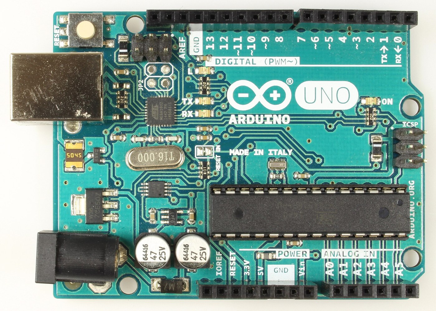


Arduino Uno R3: Assembled from Arduino's Open UNO-TH Rev3e Design Files and Flashed over ICSP
The Arduino Uno R3 is open hardware: Arduino publishes its schematic and board layout. This blueprint builds one from those files, part by part, then loads the firmware into its two processors.
Result: an Arduino Uno R3. An ATmega328P (16 MHz, 32 kB flash, 2 kB SRAM, 1 kB EEPROM) runs your programs; an ATmega16U2 turns USB into its serial link. It runs from USB (5.5 V at most) or 6-20 V at the DC jack.
Source: Arduino UNO-TH_Rev3e design files and the A000066 schematic and datasheet (Arduino, CC BY-SA). Unknown: how every bought part is made; no public source in hand says. The soldering method is ours. Picture: Wikimedia Commons.
Продвинутый
1 day
Инструкции
1
1
Get the bare board
Get the bare board
Have the two-layer board made to Arduino's UNO-TH_Rev3e board layout (the .brd file of the design files). Check it against the schematic before fitting anything.
Материалы для этого шага:
 Печатная плата1 UNO-TH Rev3e layout
Необходимые инструменты:
 Ювелирная лупа
2
2
Fit the small surface-mount parts
Fit the small surface-mount parts
Solder the chip parts to their marked places: resistor arrays RN1 (10K), RN2 and RN4 (1K), RN3 (22R); R1, R2 (1M); capacitors C1, C2, C4-C7, C10 (100n), C3, C8 (1u), C9, C11 (22p); varistors Z1, Z2; ferrite bead L1; inductor L2 (10 uH); diodes D2, D3; LEDs ON (green), L, RX, TX (yellow). Ours: flux, tweezers and hot air or a fine iron, checked under a loupe.
Материалы для этого шага:
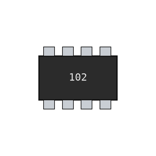 Резисторная сборка4 RN1-RN4
 Чип-резистор2 1M
 Керамический чип-конденсатор11 7x100n, 2x1u, 2x22p
 Чип-варистор2 Z1, Z2
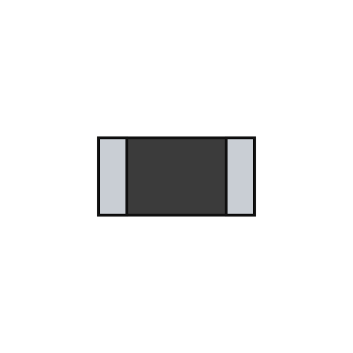 Ферритовая бусина1 L1
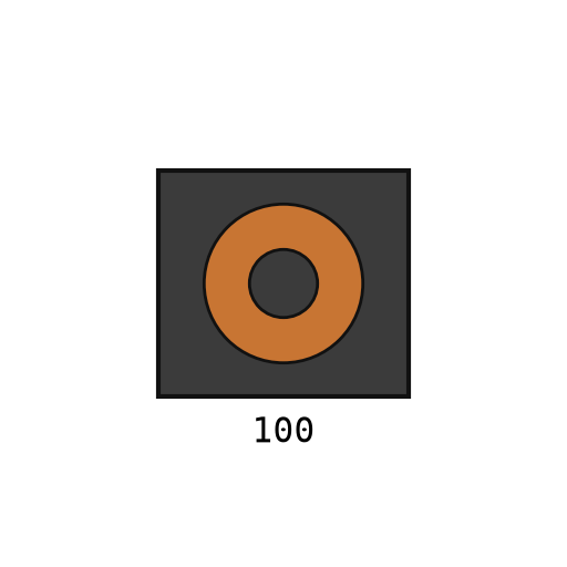 SMD-индуктивность1 L2
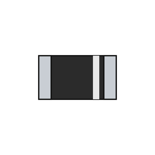 SMD-диод2 D2, D3
 Чип-светодиод4 1 green, 3 yellow
 Проволочный припой1 a little
Необходимые инструменты:
 Флюс
 Пинцет с острыми губками
 Термовоздушная паяльная станция
 ПаяльникЮвелирная лупа
3
3
Fit the power and chip parts
Fit the power and chip parts
Solder the ATmega16U2 (U3), the 16 MHz resonator Y2 and crystal Y1, the 5 V regulator NCP1117 (U1) and 3.3 V regulator LP2985 (U2), the LMV358 op-amp (U5), the FDN340P transistor (T1), the M7 diode (D1), the 500 mA resettable fuse (F1) and the 47 uF capacitors PC1, PC2 with their polarity as marked.
Материалы для этого шага:
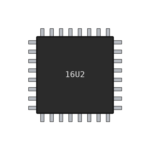 Микроконтроллер ATmega16U21 U3
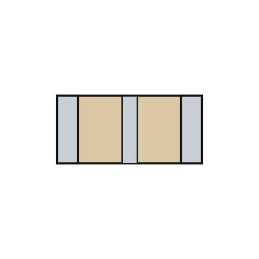 Пьезокерамический резонатор1 Y2
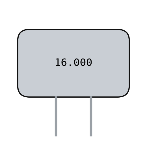 Кварцевый резонатор1 Y1
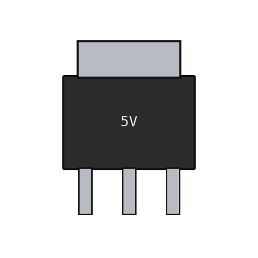 Линейный стабилизатор напряжения2 U1 5 V, U2 3.3 V
 Микросхема операционного усилителя1 U5 LMV358
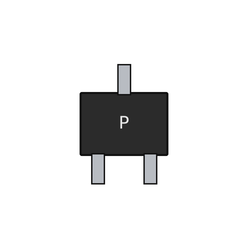 P-канальный МОП-транзистор1 T1SMD-диод1 D1 M7
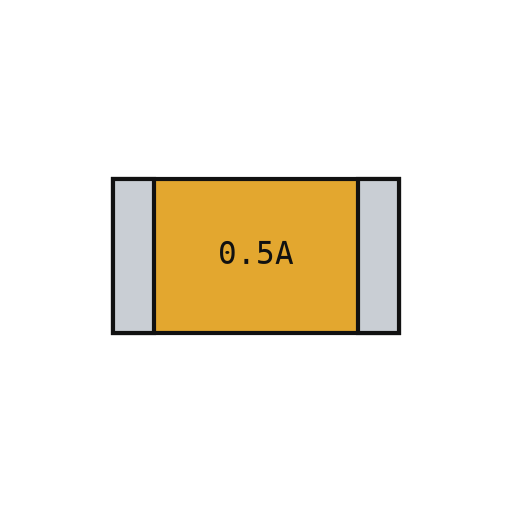 Самовосстанавливающийся предохранитель1 F1
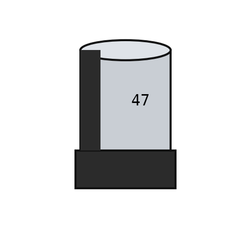 Полярный чип-конденсатор2 PC1, PC2Проволочный припой1 a little
Необходимые инструменты:
ФлюсПинцет с острыми губкамиТермовоздушная паяльная станцияПаяльникЮвелирная лупа4
4
Fit the through-hole parts
Fit the through-hole parts
Solder the USB-B socket (X2), the DC jack (X1), the reset switch, the female headers (one 10-way, two 8-way, one 6-way) and the two 2x3 ICSP headers. Seat the ATmega328P in its place (ZU4).
Материалы для этого шага:
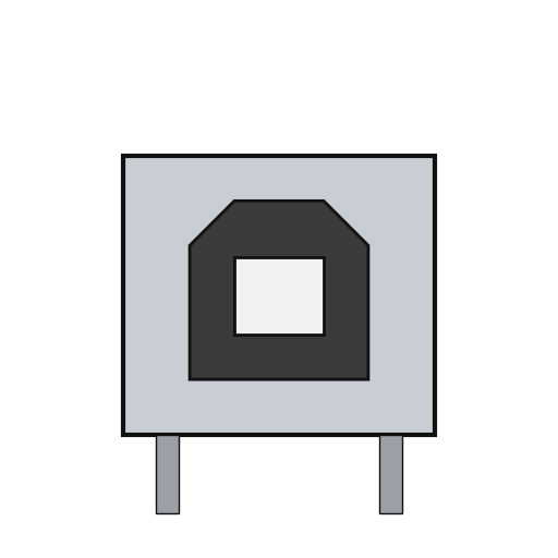 Гнездо USB-B1 X2
 Гнездо питания1 X1
 Кнопка1 RESET
 Штыревая линейка6 10x1, 2x 8x1, 6x1 female; 2x 3x2 ICSP
 Микроконтроллер ATmega328P1 ZU4Проволочный припой1 as needed
Необходимые инструменты:
Паяльник5
5
Flash and check
Flash and check
Check with a meter that 5 V and GND are not shorted. Through the ICSP headers, load the USB-to-serial firmware into the ATmega16U2 and the bootloader into the ATmega328P. Plug in USB: the green ON LED lights, and the blink test in the next step flashes the L LED. Ours: an AVR ISP programmer and a multimeter.
Материалы для этого шага:
 Прошивка Arduino Uno1 download
Необходимые инструменты:
 Мультиметр
 Программатор AVR ISP
 Кабель USB-B
6
6
The blink test
The blink test
blink_test.ino: the same check as Arduino's Blink example. Upload it over USB from the Arduino IDE with the board set to Arduino Uno; the L LED on pin 13 turns on for one second and off for one second, over and over. If it does, both processors, the USB link and the bootloader work.
blink_test.inocpp
Необходимые инструменты:
Кабель USB-BМатериалы
24- 1 UNO-TH Rev3e layoutЗаполнитель
- 4 RN1-RN4Заполнитель
- 2 1MЗаполнитель
- 11 7x100n, 2x1u, 2x22pЗаполнитель
- 2 Z1, Z2Заполнитель
- Заполнитель
- Заполнитель
- 1 D1 M7Заполнитель
- 4 1 green, 3 yellowЗаполнитель
- 1 as neededЗаполнитель
- Заполнитель
- Заполнитель
- Заполнитель
- 2 U1 5 V, U2 3.3 VЗаполнитель
- 1 U5 LMV358Заполнитель
- Заполнитель
- Заполнитель
- 2 PC1, PC2Заполнитель
- 1 X2Заполнитель
- Заполнитель
- Заполнитель
- Заполнитель
- Заполнитель
- 1 downloadЗаполнитель
Требуемые инструменты
8- Заполнитель
- Заполнитель
- Заполнитель
- Заполнитель
- 2 vendors sell this, none ship to you yetЗаполнитель
- Заполнитель
- Заполнитель
- 1 vendor sell this, none ship to you yetЗаполнитель
По этому чертежу делают
Связанные чертежи
Эти чертежи делятся знаниями — техники, материалы или принципы
CC0 Общественное достояние
Этот чертёж выпущен под лицензией CC0. Вы можете свободно копировать, изменять, распространять и использовать эту работу в любых целях без запроса разрешения.
Поддержите мейкера, покупая товары через его чертёж, где он получает Комиссию мейкера установленную продавцами, или создайте новую итерацию этого чертежа и включите его как связь в свой чертёж для распределения дохода.