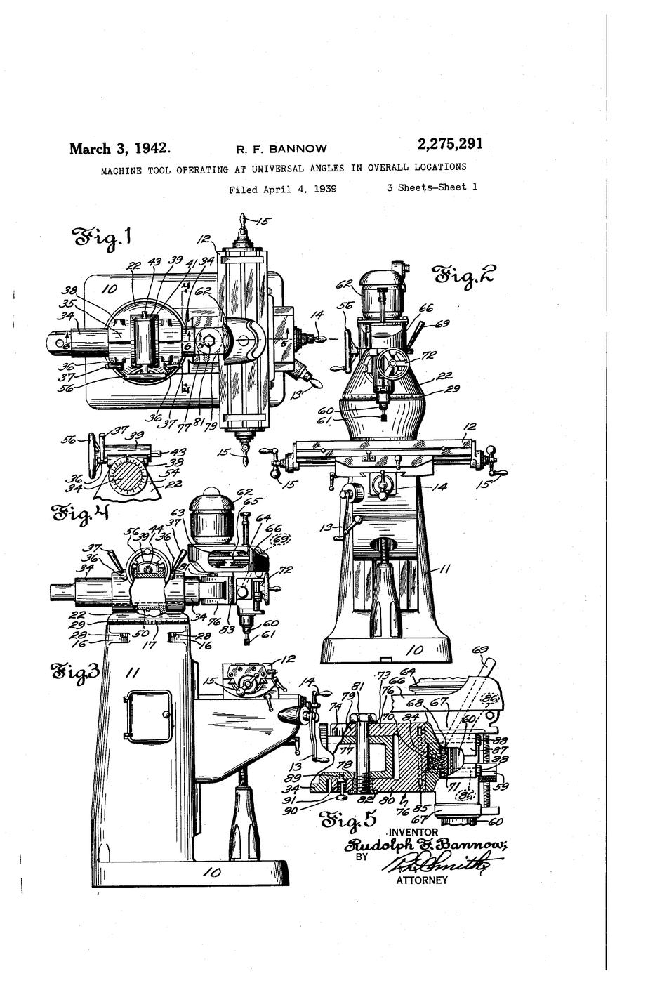


Turret Milling Head
A milling machine with a fixed head can only present its cutter one way. Every angled feature then requires the work to be moved and re-clamped — and every re-clamping is a fresh chance to lose the reference you spent the morning establishing.
US 2,275,291, “Machine Tool Operating at Universal Angles in Overall Locations”, Rudolph F. Bannow of Bridgeport, Connecticut. Filed 4 April 1939, granted 3 March 1942. An overarm slides and rotates on a swivelling turret, and the head tilts on it, so the cutter can be brought to the work “at any desired angular inclination” and reach the far ends of a long workpiece without moving it at all.
Bannow conceived the improvement in 1936; the machine was first built in 1938, the patent was applied for in 1939, and it issued in 1942. The result — the ram-and-turret vertical knee mill — became so standard that “a Bridgeport” is still how machinists name the type, whoever built it.
Инструкции
Count the freedoms you need
Count the freedoms you need
Write down what a cutter must be able to do: reach anywhere in X, Y and Z, and arrive at any angle. That is six freedoms, and a fixed head offers three.
Build the column
Build the column
Glue a 300 mm plywood upright to a plywood base. This is the column, and it must be square to the base — check it.
Материалы для этого шага:
 Лист фанеры1 лист
 Столярный клей20 мл
Необходимые инструменты:
 Слесарный угольник
Add the turret
Add the turret
Screw a plywood disc to the top of the column with a single machine screw so it rotates. That is the turret.
Материалы для этого шага:
Лист фанеры1 лист Винт с метрической резьбой #6-321 штука
Необходимые инструменты:
 Макетный нож
Add the ram
Add the ram
Cut a 200 mm plywood arm and fit it so it slides in and out across the turret. That is the overarm, or ram.
Материалы для этого шага:
Лист фанеры1 листНеобходимые инструменты:
 ЛинейкаМакетный нож
Hang the head on a pivot
Hang the head on a pivot
Pivot a small block on the end of the ram with a screw so it tilts. Mark a dowel stub in it as the spindle.
Материалы для этого шага:
Лист фанеры1 лист Деревянный шкант1 штукаВинт с метрической резьбой #6-321 штука
Mark a protractor scale on the head pivot
Mark a protractor scale on the head pivot
Draw a degree scale around the head pivot with the protractor, zero at vertical.
Материалы для этого шага:
 Картон1 лист
Необходимые инструменты:
 Транспортир
 Перманентный маркер
Reach the four corners of a long part
Reach the four corners of a long part
Lay a 250 mm bar on the base. Reach the spindle to each end using only ram and turret — the workpiece never moves.
Материалы для этого шага:
 Квадратный пруток из мягкой стали1 штука
Try the same with the ram locked
Try the same with the ram locked
Lock the ram and turret and try again. Now the part must be re-clamped to reach the far end. Count the re-clampings.
Материалы для этого шага:
 Миллиметровая бумага1 лист
Set a 30° compound angle
Set a 30° compound angle
Swivel the turret 20° and tilt the head 30°. Record both settings. Two rotations compose into one arbitrary approach direction.
Материалы для этого шага:
Миллиметровая бумага1 листНеобходимые инструменты:
ТранспортирReturn to zero and check repeatability
Return to zero and check repeatability
Return both to zero and check the spindle against the square. Any error is what a real machine calls tramming, and it must be re-checked after every head move.
Необходимые инструменты:
Слесарный угольникTram a real head with an indicator
Tram a real head with an indicator
On the benchtop mill, sweep the dial indicator in a circle across the table and record the readings at four points. Equal readings mean the spindle is square to the table.
Материалы для этого шага:
Миллиметровая бумага1 листНеобходимые инструменты:
 Малый фрезерный станок (настольный)
 Индикатор часового типа
Clamp work in the milling vise
Clamp work in the milling vise
Set the milling vise on the table and indicate its fixed jaw parallel to the table travel. A swivelling head is worthless above a crooked vise.
Необходимые инструменты:
 Станочные тиски 4 дюймаИндикатор часового типа
Write down the trade-off
Write down the trade-off
List what the ram-and-turret buys (reach, angles, small footprint) against what it costs (rigidity, and re-tramming after every move). Heavy cuts still go on fixed-bed machines.
Материалы для этого шага:
Миллиметровая бумага1 листHistory & Context
History & Context
US 2,275,291, “Machine Tool Operating at Universal Angles in Overall Locations”, Rudolph F. Bannow, Bridgeport, Connecticut. Filed 4 April 1939, granted 3 March 1942. The claims cover a two-section articulated support — an overarm that both slides longitudinally and rotates, carried on a swivelling turret head, with worm-and-wheel angular adjustment — so a cutter can work on “extreme end portions of a long piece of work” without repositioning it.
The dates, in order. Bannow (1897-1962) conceived the improvement in 1936. He and Magnus Wahlstrom, both Swedish immigrants, had founded Bridgeport Machines in 1929 and were already selling a high-speed milling attachment. The complete knee-and-column vertical mill was first built in 1938; the patent was applied for in 1939 and issued in 1942. Sources that give a single date for “the Bridgeport” are picking one of four.
Why it took over the world's small shops. One machine of modest size and cost could drill, bore, face, slot and cut at compound angles — work that previously needed several dedicated machines or a horizontal mill and a lot of setup skill. For a jobbing shop that never makes the same thing twice, flexibility beats rigidity, and this machine is the flexible one.
What it cost. Everything that swivels can be out of square. A Bridgeport-type head must be trammed, and re-trammed after any head movement — steps 10 and 11 are that discipline. Production shops cutting one part in quantity still choose fixed-bed machines, which cannot be angled and do not need to be checked.
The direct line to CNC. Fit the knee mill's three lead screws with servo motors and you have the first generation of small CNC machining centres — which is exactly what happened in the 1970s, often to second-hand Bridgeports converted in place. The machine in this blueprint is the immediate ancestor of the desktop CNC mill, and its geometry is still visible in them.
Материалы
7- 1 листЗаполнитель
- 20 млЗаполнитель
- Заполнитель
- 1 штукаЗаполнитель
- 1 листЗаполнитель
- Заполнитель
- 1 листЗаполнитель
Требуемые инструменты
8- Заполнитель
- Заполнитель
- Заполнитель
- Заполнитель
- Заполнитель
- Заполнитель
- Заполнитель
- Заполнитель
Материалы из связанных чертежей

Связанные чертежи
Эти чертежи делятся знаниями — техники, материалы или принципы


CC0 Общественное достояние
Этот чертёж выпущен под лицензией CC0. Вы можете свободно копировать, изменять, распространять и использовать эту работу в любых целях без запроса разрешения.
Поддержите мейкера, покупая товары через его чертёж, где он получает Комиссию мейкера установленную продавцами, или создайте новую итерацию этого чертежа и включите его как связь в свой чертёж для распределения дохода.