ИСКУССТВО
КРАСОТА И ЗДОРОВЬЕ
РЕМЕСЛО
КУЛЬТУРА И ИСТОРИЯ
РАЗВЛЕЧЕНИЯ
ЭКОЛОГИЯ
ЕДА И НАПИТКИ
ОБРАТНАЯ ИНЖЕНЕРИЯ
НАУКИ
СПОРТ
ТЕХНОЛОГИИ
НОСИМЫЕ УСТРОЙСТВА


Designing For the Process: A Printable Part Is a Different Shape
A model drawn without thinking about printing can usually be printed. A model drawn WITH the process in mind prints faster, stronger, with no supports and a better surface — from the same amount of design effort.
Every rung before this one is a constraint: layers are weak in one direction, overhangs have a limit, holes come out small, corners warp, walls carry the load. Design is where those stop being problems to work around and become the rules the shape is drawn to.
That is the same move as designing a casting with draft angles, or a timber frame with wood movement allowed for. The process has a grain, and a good design runs with it.
Продвинутый
4 hours
Инструкции
1
1
Chamfer the bottom, fillet the rest
Chamfer the bottom, fillet the rest
A 45-degree CHAMFER on the bottom edge of a part is self-supporting, removes the elephant-foot bulge, and makes the part easier to insert into anything. It is close to free and almost always an improvement.
Fillets elsewhere reduce stress concentration and warping, exactly as a radiused corner does on any other part. Internal corners especially: a sharp internal corner is where a printed part cracks.
But do NOT fillet the bottom edge — a bottom fillet is an overhang that starts at 90 degrees, which is the one angle nothing can print. Chamfer at the bottom, fillet above it, and that single rule removes a lot of support material.
Материалы для этого шага:
 Нить для 3D-печати (PLA)1 штука
Необходимые инструменты:
 Настольный компьютер
 Программа-слайсер файлов 3MF
 Гратосниматель
2
2
Turn overhangs into bridges and teardrops
Turn overhangs into bridges and teardrops
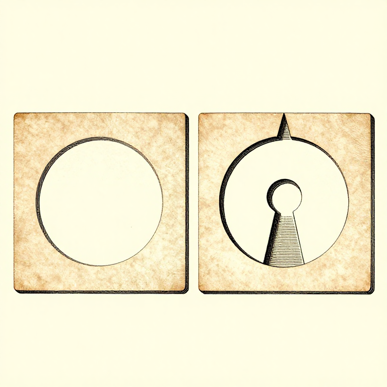
A horizontal hole printed round has an unsupported arch at the top that sags. Printed as a TEARDROP — a circle with a 45-degree point on top — it is entirely self-supporting and needs no support at all.
A hexagonal hole does the same job and takes a nut. So does simply making the top of the hole a flat bridge rather than a curve, which prints well for the reasons the overhang rung gives.
The general form: wherever the model has a surface between 45 and 90 degrees, ask whether it can become a chamfer, a bridge, or a shape with a point on top. Nearly always it can, and nearly always the result is better than supporting it.
Материалы для этого шага:
Нить для 3D-печати (PLA)1 штукаНеобходимые инструменты:
Настольный компьютерПрограмма-слайсер файлов 3MF Цифровой штангенциркуль 6 дюймов
3
3
Split the part where splitting helps
Split the part where splitting helps
A part that needs supports, or warps, or is too tall to be stable, can often be cut into two pieces that each print flat and are then glued or bolted.
Put the split where a joint is natural — at a change of section, behind a flange — and add a locating feature, a peg and socket or a dovetail, so the two halves cannot be assembled wrong. Design the clearance into one side only, as the tolerance rung sets out.
Splitting also lets each half be oriented for its own load path, which the orientation rung says is the highest-leverage decision available. A part split into two well-oriented halves can be stronger than the same part printed whole.
Материалы для этого шага:
Нить для 3D-печати (PLA)1 штукаНеобходимые инструменты:
Настольный компьютерПрограмма-слайсер файлов 3MFЦифровой штангенциркуль 6 дюймовГратосниматель4
4
Use real hardware where it belongs
Use real hardware where it belongs
Printed threads are weak, printed bearings wear, and printed springs creep. Heat-set brass inserts, steel pins, real bearings and real fasteners cost very little and remove the weakest parts of a printed assembly.
Design the pocket for them from the start: a straight bore for an insert, a captive hex pocket for a nut, a shoulder for a bearing to seat against. A pocket designed in prints perfectly; one drilled afterwards splits the part along a layer.
Which is the whole argument of this batch. The printer is one process among several, it has specific strengths and specific limits, and the best results come from using it for what it is good at and something else for the rest.
Материалы для этого шага:
Нить для 3D-печати (PLA)1 штука PETG-филамент с углеволокном1 штука
Необходимые инструменты:
Настольный компьютерЦифровой штангенциркуль 6 дюймов Набор инструментов для 3D-принтера
Материалы
2- 4 штукЗаполнитель
- PETG-филамент с углеволокном10% комиссия1 штукаЗаполнитель
Связанные чертежи
Эти чертежи делятся знаниями — техники, материалы или принципы
CC0 Общественное достояние
Этот чертёж выпущен под лицензией CC0. Вы можете свободно копировать, изменять, распространять и использовать эту работу в любых целях без запроса разрешения.
Поддержите мейкера, покупая товары через его чертёж, где он получает Комиссию мейкера установленную продавцами, или создайте новую итерацию этого чертежа и включите его как связь в свой чертёж для распределения дохода.