Сотрудничество
ИСКУССТВО
КРАСОТА И ЗДОРОВЬЕ
РЕМЕСЛО
КУЛЬТУРА И ИСТОРИЯ
РАЗВЛЕЧЕНИЯ
ЭКОЛОГИЯ
ЕДА И НАПИТКИ
ОБРАТНАЯ ИНЖЕНЕРИЯ
НАУКИ
СПОРТ
ТЕХНОЛОГИИ
НОСИМЫЕ УСТРОЙСТВА
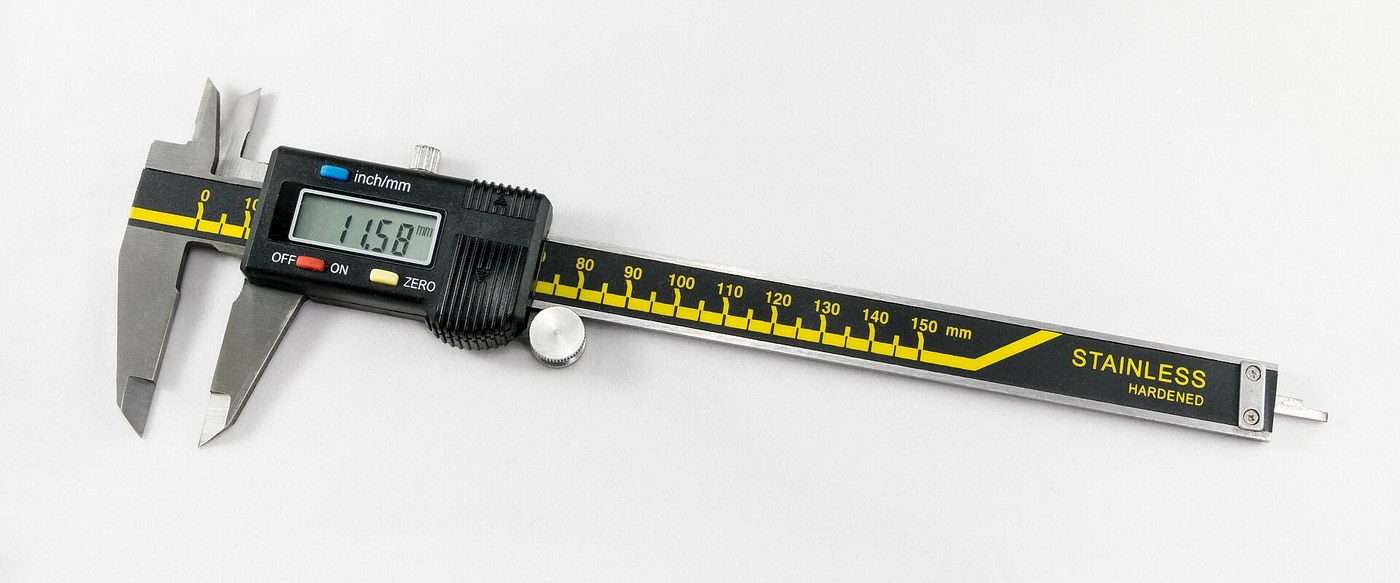


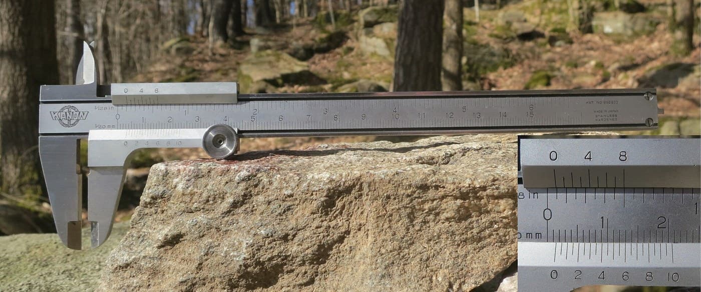
Digital Caliper: Capacitive Scale and Slider with Two-Chip Electronics (Baxter and Buehler, Starrett, 1986)
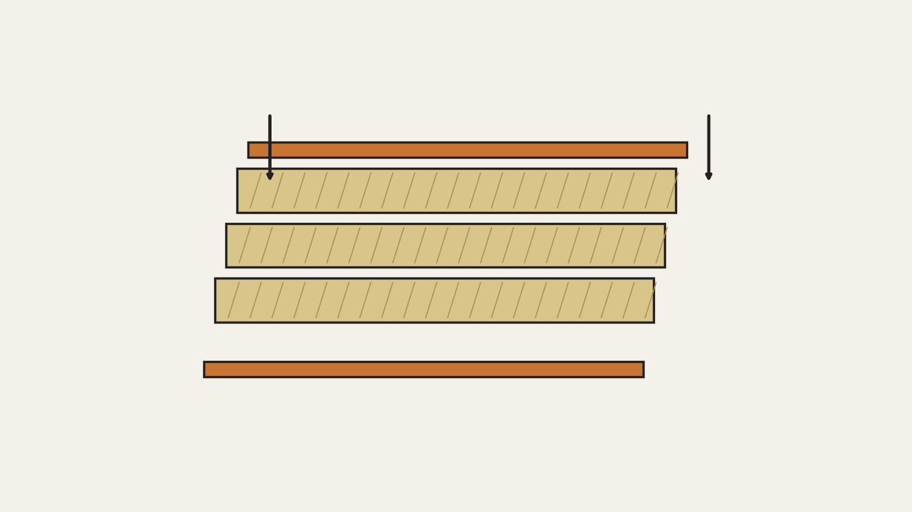
A six-inch caliper that reads out on a display. Under the slide, a strip of etched copper bars runs along the beam. Electrodes on the slider pass a signal through the bars by capacitance, and the slider's electronics count the bars crossed and work out the position in between.
Result: a digital caliper reading in inches or millimetres, repeatable to a ten-thousandth of an inch, with floating zero, peak hold and high/low limits. It runs on two 1.5 V cells at 10-50 microamps.
Source: L. K. Baxter and R. J. Buehler (L. S. Starrett Co.), US Patent 4,586,260 (1986). Unknown: the metal of the beam, slide and rod, their dimensions, the processor's program, and how the chips and display are made. Ours: the etchant, photoresist and glue. Picture: Wikimedia Commons.
Продвинутый
2 days
Инструкции
1
1
Etch the scale
Etch the scale
Etch the scale pattern onto a strip of copper-clad epoxy fibreglass with photoresist and etchant. Each copper bar is 0.40 inch long, with a wider centre 0.12 inch long and two ends 0.14 inch long. Space the bars on 0.05 inch centres: the centres sit 0.004 inch apart, the ends 0.025 inch apart. Run the pattern the full length of the scale. Ours: dry film resist and ferric chloride.
Материалы для этого шага:
 Заготовка печатной платы (фольгированная)1 strip, length of the beam
Необходимые инструменты:
 Сухой плёночный фоторезист
 Раствор хлорида железа(III)
 Химически стойкие перчатки
2
2
Fix the scale into the beam
Fix the scale into the beam
The beam is a metal bar with the fixed outside and inside jaws at one end, a wide shallow channel in its face and a second channel along its back. Fix the scale permanently into the face channel, copper up. The patent allows etching before or after this step. Not given: the metal, the dimensions and how the scale is fixed. Ours: epoxy.
Материалы для этого шага:
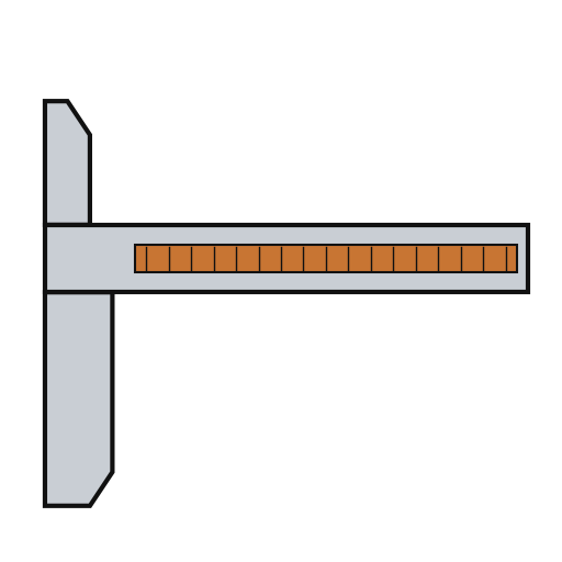 Штанга штангенциркуля1 with integral jaws
 Двухкомпонентная эпоксидка1 a little
Необходимые инструменты:
 Неизвестные размеры
3
3
Fit the parts to the circuit
Fit the parts to the circuit
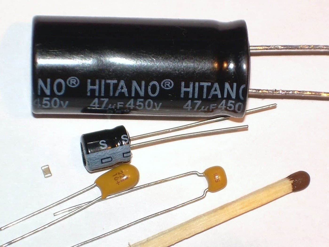
The circuit is one folded piece: a double-sided slider board joined by a flexible hinge to a circuit board. Its bottom face has two pickup electrodes, 0.750 x 0.110 inch and 0.0625 inch apart. On each side of them is an interdigitated transmitter array: fingers 0.115 inch long on 0.025 inch spacing, opening to 0.0375 inch at the centre. On the circuit board, solder or wire-bond the two chips: an NEC uPD7503 3 V processor (768 bits RAM, 2 kB ROM) and a CMOS gate array. Then fit the LCD, the 100 kHz crystal, the integrating capacitor and the MODE and SET buttons. Not given: the processor's program. Ours: a capacitor from a kit.
Материалы для этого шага:
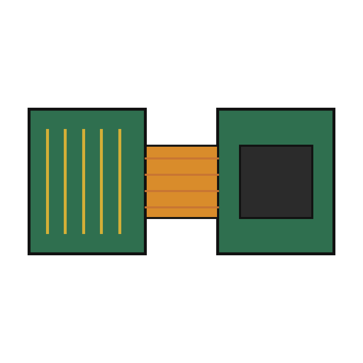 Гибко-жёсткая печатная плата1 slider board + circuit board
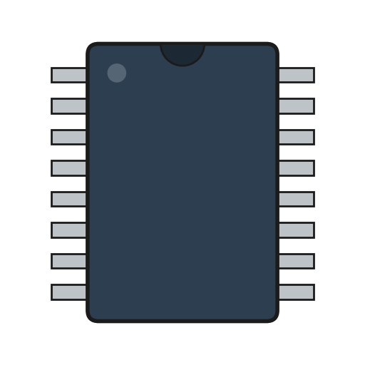 Интегральная микросхема2 uPD7503 CPU, CMOS gate array
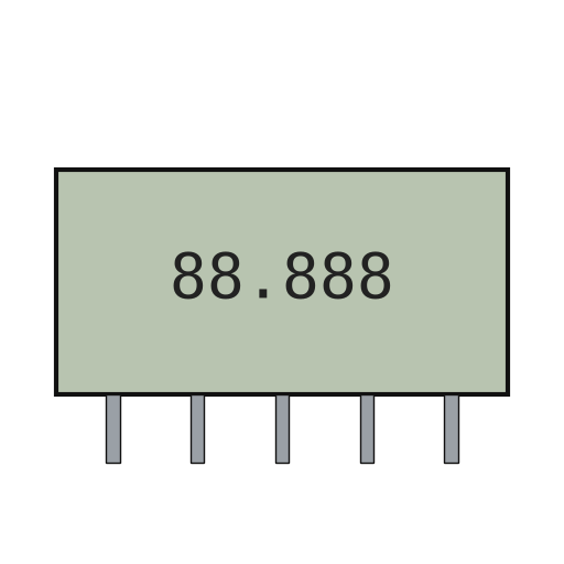 Сегментный ЖК-индикатор1 5 digits
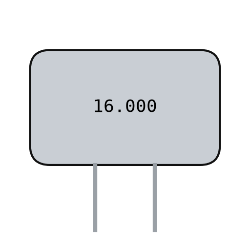 Кварцевый резонатор1 100 kHz
 Набор конденсаторов1 one integrating capacitor
 Кнопка2 MODE, SET
 Проволочный припой1 a little
Необходимые инструменты:
 Паяльник
4
4
Build the slide
Build the slide
The slide frame wraps the back and edges of the beam and carries the movable jaws. Fix it to the depth rod, which runs in the back channel of the beam; the rod's free end is the depth gauge. Put the moulded plastic housing between the frame ends. Fasten two metal wear strips under the slider board, one on each side of the scale. They ride on the beam and connect the board's copper to it. Not given: the metal and sizes.
Материалы для этого шага:
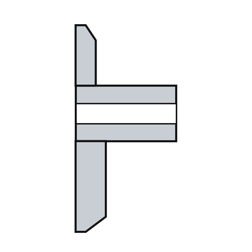 Рамка штангенциркуля1 with jaws
 Неизвестный металл1 depth rod and two wear strips
 Корпус рамки1 штука
Необходимые инструменты:
Неизвестные размеры Набор точных отвёрток
5
5
Assemble and check
Assemble and check
Fold the circuit into the housing recess, slider board facing the scale, and screw it to the frame. The electrodes must lie parallel to the scale bars at every point of travel. Put the two 1.5 V cells (the patent says 'zinc oxide') in the battery pockets of the circuit. The display shows five digits, a ten-thousandths bar graph, a minus sign and 'mm', plus PEAK, LOW, HIGH and LIMIT. Ours: check the reading against a vernier caliper.
Материалы для этого шага:
 Машинные винты2 штук
 Дисковый элемент питания 1,5 В2 штук
Необходимые инструменты:
Набор точных отвёрток Штангенциркуль
Материалы
15- 1 strip, length of the beamЗаполнитель
- 1 with integral jawsЗаполнитель
- 1 a littleЗаполнитель
- 1 slider board + circuit boardЗаполнитель
- 2 uPD7503 CPU, CMOS gate arrayЗаполнитель
- 1 5 digitsЗаполнитель
- 1 100 kHzЗаполнитель
- 1 one integrating capacitorЗаполнитель
- Заполнитель
- 1 a littleЗаполнитель
- 1 with jawsЗаполнитель
- 1 depth rod and two wear stripsЗаполнитель
- 1 штукаЗаполнитель
- 2 штукЗаполнитель
- Заполнитель
Требуемые инструменты
7- Заполнитель
- Заполнитель
- Заполнитель
- Заполнитель
- 2 vendors sell this, none ship to you yetЗаполнитель
- Заполнитель
- Заполнитель
Материалы из связанных чертежей

По этому чертежу делают

Связанные чертежи
Эти чертежи делятся знаниями — техники, материалы или принципы
CC0 Общественное достояние
Этот чертёж выпущен под лицензией CC0. Вы можете свободно копировать, изменять, распространять и использовать эту работу в любых целях без запроса разрешения.
Поддержите мейкера, покупая товары через его чертёж, где он получает Комиссию мейкера установленную продавцами, или создайте новую итерацию этого чертежа и включите его как связь в свой чертёж для распределения дохода.