Сотрудничество
ИСКУССТВО
КРАСОТА И ЗДОРОВЬЕ
РЕМЕСЛО
КУЛЬТУРА И ИСТОРИЯ
РАЗВЛЕЧЕНИЯ
ЭКОЛОГИЯ
ЕДА И НАПИТКИ
ОБРАТНАЯ ИНЖЕНЕРИЯ
НАУКИ
СПОРТ
ТЕХНОЛОГИИ
НОСИМЫЕ УСТРОЙСТВА
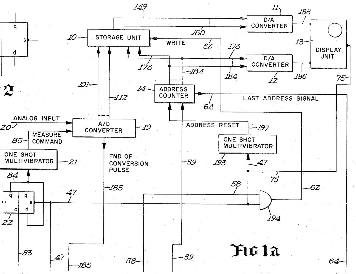


Digital Oscilloscope: Waveform Stored in Memory and Shown on a CRT (Schumann, Nicolet, US 3,816,815, 1974)
An oscilloscope with a memory. After a trigger, an analog-to-digital converter measures the input at regular intervals and writes each reading into its own memory register, replacing the old one. The screen then shows the memory: each register's number sets the beam's height, its address sets the beam's place across. The last waveform can be held on the screen as long as you like.
Result: a digital storage oscilloscope with 4,096 points of 12 bits, refresh and hold modes and single-shot capture.
Source: R. W. Schumann (Nicolet), US 3,816,815 (1974). Unknown: sample rate, bandwidth, voltages and the parts used. Picture: the patent drawing.
Эксперт
Unknown
Инструкции
1
1
Sample and convert the input
Sample and convert the input
Bring the analog input to an analog-to-digital converter, through a BNC socket. A sampling oscillator, divided by four by two flip-flops so the first reading comes soon after the sweep starts, fires a one-shot multivibrator that gives the converter its measure command. The converter holds each 12-bit result on its output lines and signals the end of each conversion. Ours: a BNC socket. Not given: the sample rate.
Материалы для этого шага:
 Аналого-цифровой преобразователь1 12-bit converter
 Тактовый генератор1 sampling oscillator
 Набор логических микросхем1 flip-flops, one-shots, gates
 Набор коаксиальных разъёмов (BNC / SO-239)1 input socket
Необходимые инструменты:
 Паяльник
 Инструмент для снятия изоляции
2
2
Store each reading in memory
Store each reading in memory
Wire an integrated-circuit memory of 4,096 registers, 12 bits each, that can be read without changing it. A 12-bit address counter picks the register. On each write command the register at the current address takes the last reading from the converter, and the counter steps on. When the sweep starts, a one-shot resets the counter to zero. When it reaches the last address, its last-address signal ends the sweep.
Материалы для этого шага:
 Полупроводниковая память1 4,096 x 12-bit store
Необходимые инструменты:
ПаяльникИнструмент для снятия изоляции3
3
Drive the CRT from the memory
Drive the CRT from the memory
Feed the addressed register's number to one digital-to-analog converter and the address to a second. Their outputs drive the vertical and horizontal deflection plates of a cathode-ray tube, so the beam always stands at the height of the stored reading and at the place of its address. Wire the sweep line to the tube's intensifier, to brighten the trace while a waveform is being taken.
Материалы для этого шага:
 Цифро-аналоговый преобразователь2 vertical and horizontal
 Электронно-лучевая трубка1 display tube
Необходимые инструменты:
ПаяльникИнструмент для снятия изоляции4
4
Wire the trigger and the modes
Wire the trigger and the modes
A trigger input, usually from the leading edge of the input waveform, starts the sweep, once a measure flip-flop has armed it. Put a two-position mode switch on the face: MODE I and MODE II. Add a push button in the probe, a switch on the panel and an external initiate input; each goes through a flip-flop that removes contact bounce. Two more oscillators step the memory round to refresh the display between waveforms. Mount it all in a case with its supply. Ours: toggle switches, an aluminium case, a DC supply. Not given: the supply voltages.
Материалы для этого шага:
Тактовый генератор2 display sequencing oscillators Тумблер2 mode and panel switches
 Кнопка1 probe switch
 Алюминиевый корпус1 case
Необходимые инструменты:
 Источник питания постоянного тока
 Сверлильный станокПаяльник
5
5
Capture and hold a waveform
Capture and hold a waveform
In MODE I, refresh: each new triggered waveform replaces the last on the screen. Press the probe or panel switch to hold: new waveforms are rejected and the last one stays on the screen. In MODE II the screen normally holds; on command, it takes the first waveform after the command, stores it and shows it steadily. Test it with a known signal.
Необходимые инструменты:
 Генератор сигналов
Материалы
10- 1 12-bit converterЗаполнитель
- 2 display sequencing oscillatorsЗаполнитель
- 1 flip-flops, one-shots, gatesЗаполнитель
- 1 input socketЗаполнитель
- 1 4,096 x 12-bit storeЗаполнитель
- 2 vertical and horizontalЗаполнитель
- 1 display tubeЗаполнитель
- Заполнитель
- Заполнитель
- 1 caseЗаполнитель
По этому чертежу делают

Связанные чертежи
Эти чертежи делятся знаниями — техники, материалы или принципы
CC0 Общественное достояние
Этот чертёж выпущен под лицензией CC0. Вы можете свободно копировать, изменять, распространять и использовать эту работу в любых целях без запроса разрешения.
Поддержите мейкера, покупая товары через его чертёж, где он получает Комиссию мейкера установленную продавцами, или создайте новую итерацию этого чертежа и включите его как связь в свой чертёж для распределения дохода.