Сотрудничество
ИСКУССТВО
КРАСОТА И ЗДОРОВЬЕ
РЕМЕСЛО
КУЛЬТУРА И ИСТОРИЯ
РАЗВЛЕЧЕНИЯ
ЭКОЛОГИЯ
ЕДА И НАПИТКИ
ОБРАТНАЯ ИНЖЕНЕРИЯ
НАУКИ
СПОРТ
ТЕХНОЛОГИИ
НОСИМЫЕ УСТРОЙСТВА
Turning-Tub Churn: A Crank Spins the Tub on a Geared Pedestal Against Two Fixed Triangular Beaters Held From Standards
Buttercup

Создано

Buttercup

11. ноябрь 2026IE
0
0
0
0
0

Turning-Tub Churn: A Crank Spins the Tub on a Geared Pedestal Against Two Fixed Triangular Beaters Held From Standards

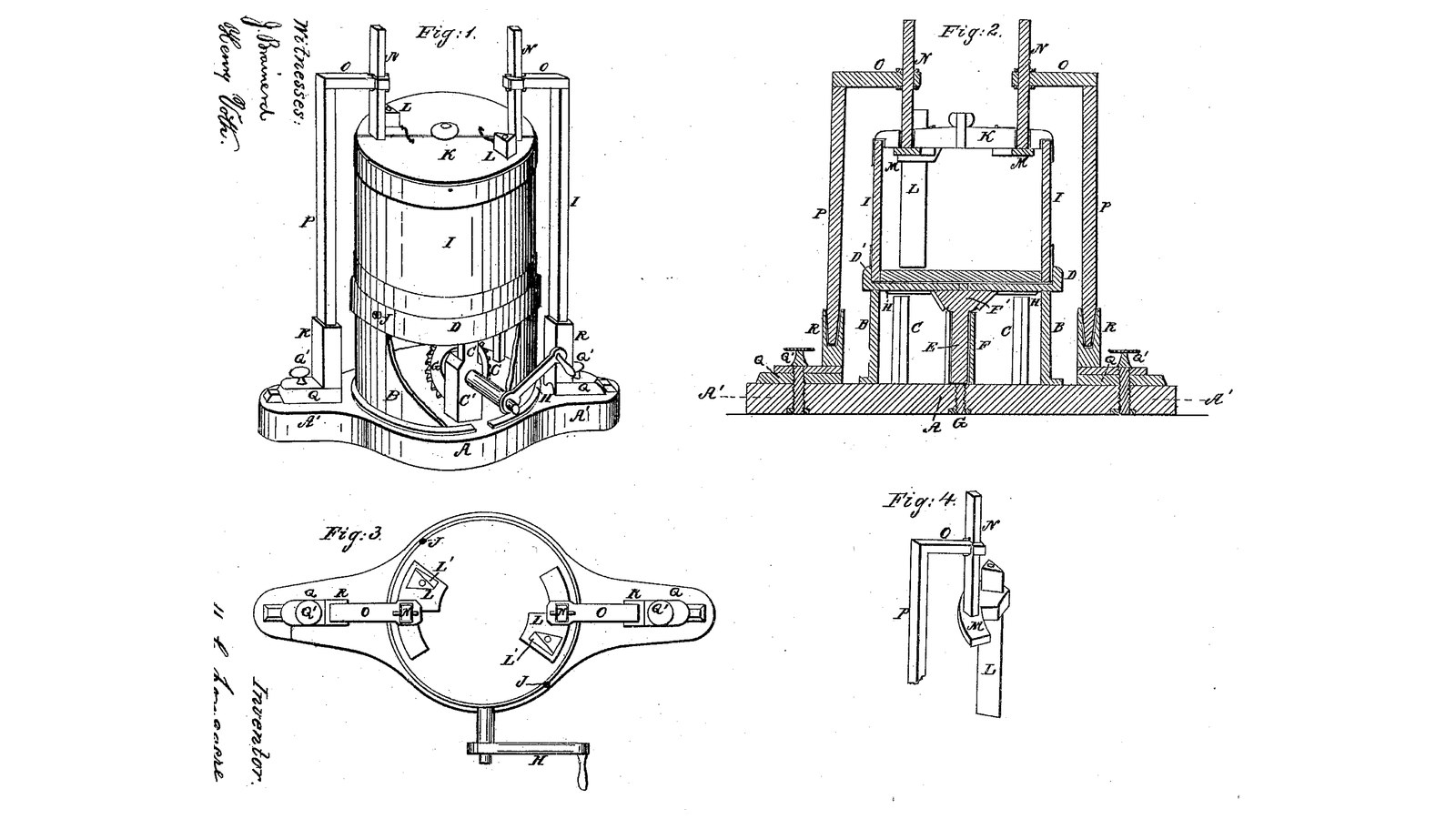
M. C. Longacre of Cleveland, Ohio, received US 31,355, dated 5 February 1861, for a churn that turns the tub instead of the dasher. A crank and bevel gears hidden in a drum on the base spin a disk on which the tub, or a common pail, stands. Two triangular wooden beaters, each with a hole along it for air, hang still inside the tub from arms on two standards and can be set nearer the wall or deeper. The tub throws the cream outward and the beaters throw it back. The patent gives no sizes; every size here is ours.
Продвинутый
About 3 days

Инструкции

1

How fast to turn the tub

Загрузка блокнота Jupyter…
2

A turning vessel against a fixed break, a year and a half before

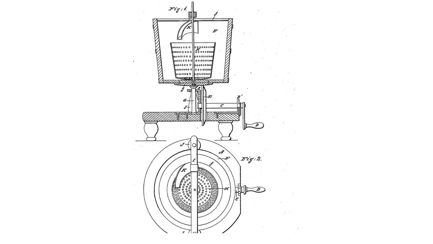
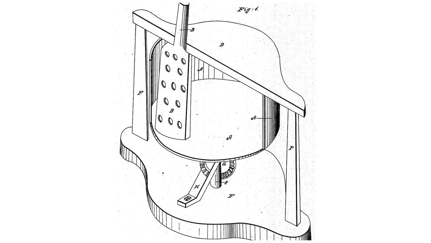
Harsha also turns the vessel against something fixed. Longacre stands the tub upright on a geared pedestal and makes the fixed beaters adjustable.
3

Read US 31,355

"Now, if the crank H is turned, the tub I, and disk D will receive a rotary motion, and the centrifugal force, tending to throw the fluid to the walls of the tub, the beaters at the same time tending to throw the same fluid back toward the center, the cream or milk has thus two forces constantly acting upon it, one a centrifugal, and the other a centripetal."
4

Base A, cylinder B and posts C

Glue up a hardwood base A 40 mm thick, a 400 mm circle with ends 120 mm wide running out to 700 mm overall. Cut a 30 mm slot 120 mm long along each end for the standards' feet. Roll a strip of 1.5 mm stainless sheet 168 mm wide into a cylinder B 310 mm across, rivet the lap, and screw it to the base through small tabs. Screw three hardwood posts C 40 mm square and 170 tall inside it, 110 mm from the centre and a third of a turn apart, the first at the back. Bore the cylinder 16.6 mm at the front, 97 mm up, for the crank shaft.

Материалы для этого шага:

Доска из твёрдой древесиныДоска из твёрдой древесины3 штук
Столярный клейСтолярный клей1 штука
Лист нержавеющей сталиЛист нержавеющей стали1 штука
Вытяжные заклёпкиВытяжные заклёпки6 штук
Шурупы по деревуШурупы по дереву16 штук

Необходимые инструменты:

Циркулярный станокЦиркулярный станок
КомпасКомпас
ЭлектролобзикЭлектролобзик
Ручной фрезерРучной фрезер
Ножницы по металлуНожницы по металлу
Набор заклёпочникаНабор заклёпочника
Аккумуляторная дрельАккумуляторная дрель
Набор свёрлНабор свёрл
Струбцина с направляющейСтрубцина с направляющей
Набор отвёртокНабор отвёрток
5

Print the cog wheel E'

The cog wheel E' on the spindle under the disk: 14 teeth, module 2.5, 16.2 mm bore, its hub up. PETG, 0.2 mm layers, 30 % infill, 4 walls.
Файл дизайнаSTLCC0 - Free
6

Print the driving wheel G

The driving wheel G on the crank shaft: a crown wheel of 42 teeth, module 2.5, 16.2 mm bore. PETG, 0.2 mm layers, 30 % infill, 4 walls.
Файл дизайнаSTLCC0 - Free
7

Step G, pipe box F, spindle E, gears and crank H

Bore the base's centre 8.4 mm and run an M8 bolt up through it with a nut each side, its head the step G, so it can be screwed up or down. Set a stainless tube F 30 mm long round it. Cut a 16 mm stainless spindle E 185 mm long; pin the cog wheel E' on it with its teeth 150 mm above the base. Screw a hardwood bearing block C' 40 x 25 x 120 mm to the base 55 to 80 mm in front of the centre, bored 16.6 mm across 97 mm up. Run a 16 mm stainless crank shaft 250 mm long through the cylinder and block, with the wheel G pinned on its inner end meshing E' from below and its end stopping clear of the spindle, a shaft collar against the block, and a crank H of mild steel flat bar, 100 mm throw, with a hardwood handle.

Материалы для этого шага:

Набор шестигранных болтовНабор шестигранных болтов1 штука
Шестигранная гайкаШестигранная гайка2 штук
Труба из нержавеющей сталиТруба из нержавеющей стали1 штука
Пруток из нержавеющей сталиПруток из нержавеющей стали2 штук
Доска из твёрдой древесиныДоска из твёрдой древесины1 штука
Shaft CollarShaft Collar1 штука
ШплинтШплинт3 штук
Полоса из малоуглеродистой сталиПолоса из малоуглеродистой стали1 штука

Шканты из твёрдой древесиныШканты из твёрдой древесины1 штука
Филамент PETGФиламент PETG1 штука

Необходимые инструменты:

3D-принтер FDM3D-принтер FDM
Аккумуляторная дрельАккумуляторная дрель
Набор свёрлНабор свёрл
Ножовка по металлуНожовка по металлу
Напильники (ручной напильник)Напильники (ручной напильник)
Слесарные тискиСлесарные тиски
Разводной ключРазводной ключ
Набор отвёртокНабор отвёрток
8

Disk D, flange D', bead H and tub I

Cut an 18 mm HDPE disk D 330 mm across, bore it 16.2 mm at the centre and fix it on the spindle's top. Screw under it a bead H, an HDPE ring 230 mm across outside and 210 inside, 2 mm thick, and on top a flange ring D' 300 mm across outside and 282 inside, 15 high, that the bucket's foot just drops into. Screw the step G up until the bead just touches the posts' tops. Use a 20-litre food-grade bucket as the tub I; for the patent's set screws J, two machine screws through the flange bearing on the bucket's foot.

Материалы для этого шага:

Лист ПНДЛист ПНД2 штук
Шурупы по деревуШурупы по дереву12 штук
Ведро на 20 литровВедро на 20 литров1 штука
Набор шестигранных болтовНабор шестигранных болтов2 штук

Необходимые инструменты:

КомпасКомпас
ЭлектролобзикЭлектролобзик
Набор перовых свёрлНабор перовых свёрл
Аккумуляторная дрельАккумуляторная дрель
Набор свёрлНабор свёрл
Разводной ключРазводной ключ
Набор отвёртокНабор отвёрток
9

Beaters L, supports M, stems N, arms O, standards P and cover K

Plane two hardwood beaters L to a triangle 40 mm a side, 330 long, and bore a 10 mm hole through each lengthwise for air. Cut two hardwood supports M 50 x 40 x 65 mm with a triangular socket below for a beater's top and a 20 mm square socket above for a stem; glue the beaters in. Cut two hardwood stems N 20 mm square, 170 long, and fit each in its support. Make two standards P 40 x 40 mm, 650 tall, each on a foot Q 60 x 80 x 20 mm with a carriage bolt down through the base's slot and a wing nut Q' under it, so the standards slide in and out; let each stand in a socket in its foot (R) so it lifts out. Fix a hardwood arm O 30 mm square across the top of each standard, reaching in to its stem, with a 20 mm square hole and a wing-nut clamp bolt so the stem can be set higher or lower. Cut an HDPE cover K 304 mm across in two halves, notched for the stems.

Материалы для этого шага:

Доска из твёрдой древесиныДоска из твёрдой древесины2 штук
Столярный клейСтолярный клей1 штука
Болт с полукруглой головкойБолт с полукруглой головкой4 штук
Гайка-барашекГайка-барашек4 штук
Плоская шайбаПлоская шайба4 штук
Лист ПНДЛист ПНД1 штука

Необходимые инструменты:

Циркулярный станокЦиркулярный станок
Набор стамесок по деревуНабор стамесок по дереву
Аккумуляторная дрельАккумуляторная дрель
Набор свёрлНабор свёрл
Набор перовых свёрлНабор перовых свёрл
ЭлектролобзикЭлектролобзик
Разводной ключРазводной ключ
РулеткаРулетка
10

The build in 3D

FreeCAD model of this build, the drum, disk and tub cut open: the base with its slotted ends, the drum, posts and bearing block, the step, spindle, cog wheel and driving wheel with the crank, the disk with its bead and flange, the bucket, and the two beaters hanging from their supports, stems, arms and standards.
Файл дизайнаBLENDCC0 - Free
11

Churn

Set the bucket in the flange and pour in about 8 litres of heavy cream at about 15 °C, checked with the thermometer. Set the beaters close to the wall and reaching near the bottom without touching, and lay on the cover halves. Turn the crank steadily, timing it, not so fast that the cream climbs to the rim. When the butter comes, keep turning a little so it gathers in a mass. Lift off the cover and beaters, lift the bucket off the disk, take out the butter, pour the buttermilk into a bowl, wash the butter in cold water until it runs clear, salt and weigh it.

Материалы для этого шага:

Жирные сливкиЖирные сливки8 l
Крупная морская сольКрупная морская соль1 штука
ВодаВода1 штука

Необходимые инструменты:

Термометр с оставляемым щупомТермометр с оставляемым щупом
СекундомерСекундомер
Цифровые кухонные весыЦифровые кухонные весы
Большая миска из нержавеющей сталиБольшая миска из нержавеющей стали
12

Troubleshooting

Turning-tub churn troubleshooting.

Flow

Loading...
13

History and honest limits

**M. C. Longacre** of Cleveland, Cuyahoga County, Ohio, assignor to himself and R. R. Herrick, US 31,355, 5 February 1861, "Churn". He claimed "rotating the body of the churn in a vertical position by means of the disk (C) or its equivalent, when connected with the stationary dashers (L) arranged as described, for the purpose of adjusting the same both vertically and horizontally". His text uses the letters G and H each for two parts (the step and the driving wheel; the bead and the crank). His gears were bevel wheels; ours are a printed pinion and crown wheel, and our drum is stainless sheet. The patent gives no sizes; every size here is ours.

Материалы

22

Требуемые инструменты

22

Файлы дизайна

3

CC0 Общественное достояние

Этот чертёж выпущен под лицензией CC0. Вы можете свободно копировать, изменять, распространять и использовать эту работу в любых целях без запроса разрешения.

Поддержите мейкера, покупая товары через его чертёж, где он получает Комиссию мейкера установленную продавцами, или создайте новую итерацию этого чертежа и включите его как связь в свой чертёж для распределения дохода.

Обсуждение

(0)

Войти чтобы присоединиться к обсуждению

Загрузка комментариев...