

Cylindrical Grinding Machine
Measuring to a thousandth is useless if nothing can be made to a thousandth. Grinding is how metrology stopped being a laboratory exercise and became manufacturing.
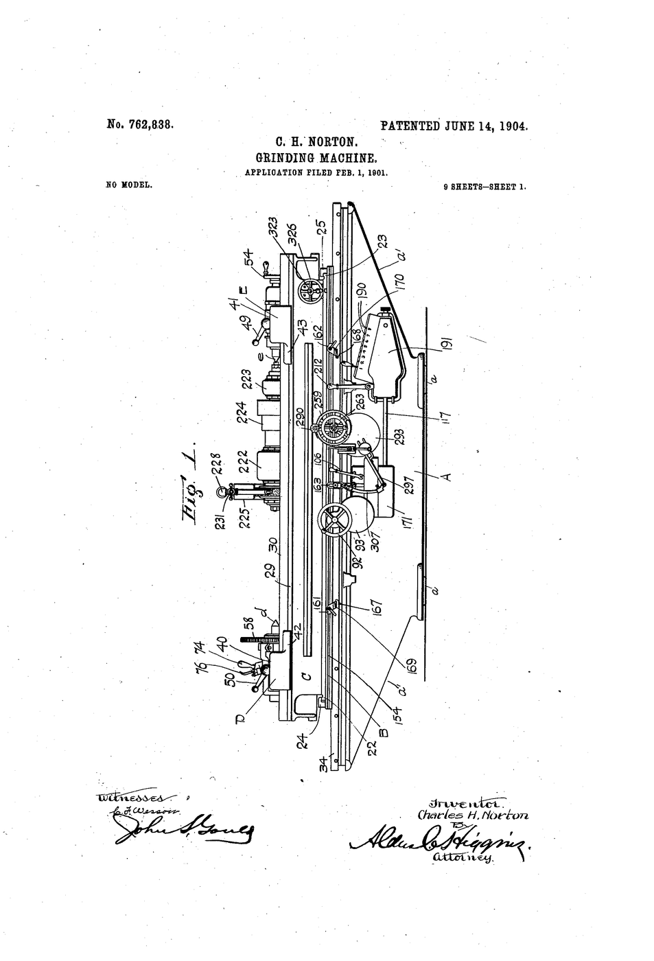
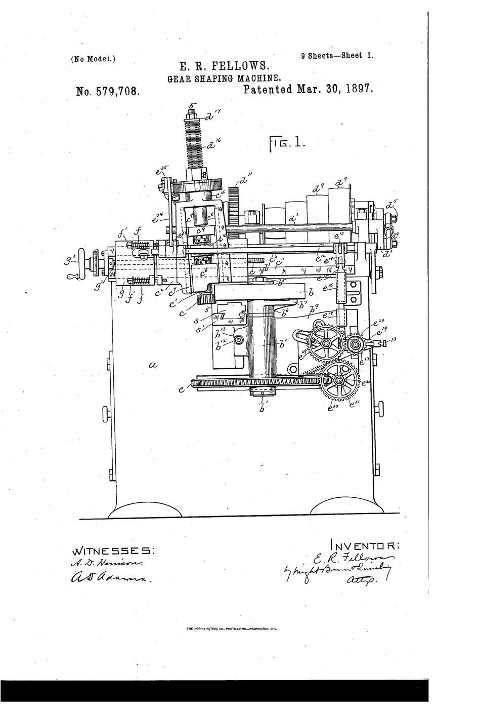
US 762,838, “Grinding-Machine”, Charles H. Norton of Worcester, Massachusetts, filed 1 February 1901 and granted 14 June 1904, assigned to the Norton Grinding Company. Norton's argument, in his own words, was “great rigidity of parts, minute accuracy in grinding heavy work, simplicity and cheapness of construction”.
Rigidity is the insight. Everyone before him built grinders light, because grinding was thought of as delicate finishing. Norton built a machine weighing over 6,800 kg with a wide wheel and took heavy cuts — and got better accuracy, not worse, because a rigid machine does not flex away from the work.
Инструкции
Read the claim before you build
Read the claim before you build
Norton claims rigidity as the route to accuracy — the opposite of the intuition that delicate work needs a delicate machine. Write down why you would expect the opposite.
Feel flex in a thin beam
Feel flex in a thin beam
Hold the steel ruler flat, press its end sideways. It bends easily. Now turn it on edge and press again. Same steel, far stiffer. Shape beats material.
Необходимые инструменты:
 Линейка
Measure the deflection
Measure the deflection
Clamp the ruler flat over the board's edge and press with a known steady push; measure the deflection with the dial indicator.
Материалы для этого шага:
 Плоская деревянная доска1 штука
Необходимые инструменты:
 Индикатор часового типаЛинейка
Repeat on edge
Repeat on edge
Repeat with the ruler on edge. Record the much smaller deflection. This ratio is why Norton's machine was heavy.
Материалы для этого шага:
 Миллиметровая бумага1 лист
Необходимые инструменты:
Индикатор часового типаSand a rod by hand
Sand a rod by hand
Sand the brass rod by hand for one minute, turning as you go.
Необходимые инструменты:
 Латунный пруток
Measure what hand work achieved
Measure what hand work achieved
Measure the rod at four points around and along with the micrometer. Record the spread.
Материалы для этого шага:
Миллиметровая бумага1 листНеобходимые инструменты:
 МикрометрЛатунный пруток
Build a rigid rest
Build a rigid rest
Glue two blocks to the board so the rod is supported close to where it is being worked. Support near the cut is the whole trick.
Материалы для этого шага:
Плоская деревянная доска1 штука Столярный клей5 мл
Work the rod again with support
Work the rod again with support
Sand again, this time with the rod held in the rest and rotated steadily.
Необходимые инструменты:
Латунный прутокMeasure and compare
Measure and compare
Measure the four points again. Compare the spread with step 6. Same abrasive, same hand, better geometry.
Материалы для этого шага:
Миллиметровая бумага1 листНеобходимые инструменты:
МикрометрCheck roundness with the indicator
Check roundness with the indicator
Roll the rod under the dial indicator on the surface plate. The needle sweep is out-of-roundness.
Необходимые инструменты:
Индикатор часового типа Поверочная плитаЛатунный пруток
Deliberately support it badly
Deliberately support it badly
Remove one support and work the rod again. Measure. Chatter and taper appear immediately.
Необходимые инструменты:
Латунный прутокМикрометрCheck against a gauge
Check against a gauge
Set a feeler stack to your target and test whether the rod passes. Grinding without a gauge is just polishing.
Необходимые инструменты:
 Набор щупов
Grind to a stated tolerance
Grind to a stated tolerance
Set a target such as ±0.05 mm and work until every measured point falls inside it. Record how many attempts it took.
Материалы для этого шага:
Миллиметровая бумага1 листНеобходимые инструменты:
МикрометрЛатунный прутокHistory & Context
History & Context
US 762,838, “Grinding-Machine”, Charles H. Norton, Worcester, Massachusetts, filed 1 February 1901, granted 14 June 1904, assigned to the Norton Grinding Company.
A date correction. Popular accounts date this machine to 1900 and often imply the patent is contemporaneous. 1900 is when Norton designed it; the application was filed in February 1901 and took more than three years to issue.
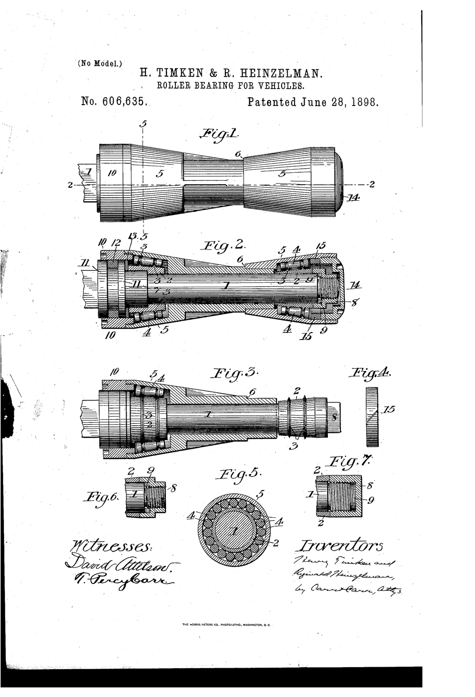
What it did to industry. Norton's grinder could finish a cylindrical part far faster than anything before it while holding about a quarter of a thousandth of an inch. Henry Ford bought them in quantity for Model T production. Grinding a crankshaft or a bearing race to a repeatable diameter is precisely what makes engines mass-producible — the Timken tapered roller bearing linked here is one of the parts that depends on it.
Why rigidity beats delicacy. A cutting force pushes the tool away from the work. If the machine flexes, the cut is shallower than commanded, and worse, the flex varies as the force varies, so the error is not even constant. A heavy machine deflects less, so what you command is what you get. This is one of the genuinely counter-intuitive results in engineering, and it is why precision machine tools are massive lumps of cast iron rather than elegant frames.
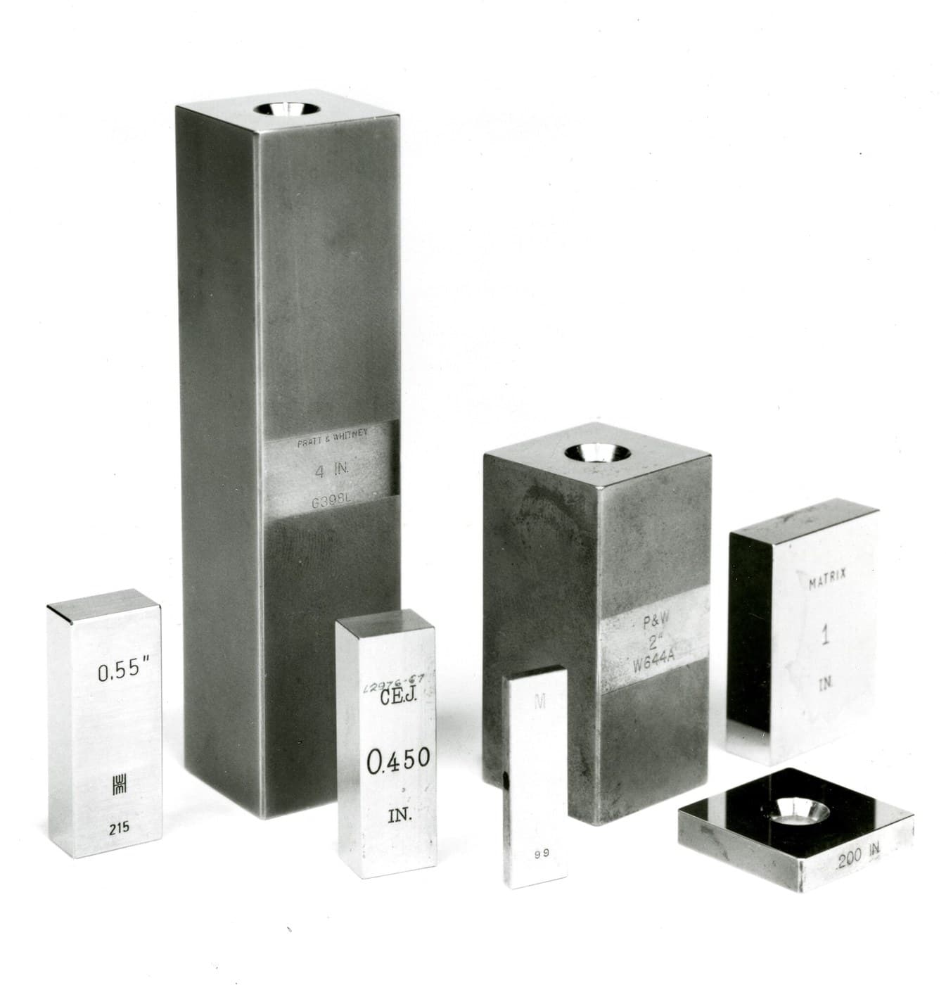
Where it sits. Johansson's blocks, linked here, define the size. Norton's machine produces it. Without both, a tolerance on a drawing is a wish.
Материалы
3- 1 штукаЗаполнитель
- 1 листЗаполнитель
- 5 млЗаполнитель
Материалы из связанных чертежей

Связанные чертежи
Эти чертежи делятся знаниями — техники, материалы или принципы
CC0 Общественное достояние
Этот чертёж выпущен под лицензией CC0. Вы можете свободно копировать, изменять, распространять и использовать эту работу в любых целях без запроса разрешения.
Поддержите мейкера, покупая товары через его чертёж, где он получает Комиссию мейкера установленную продавцами, или создайте новую итерацию этого чертежа и включите его как связь в свой чертёж для распределения дохода.