Сотрудничество
ИСКУССТВО
КРАСОТА И ЗДОРОВЬЕ
РЕМЕСЛО
КУЛЬТУРА И ИСТОРИЯ
РАЗВЛЕЧЕНИЯ
ЭКОЛОГИЯ
ЕДА И НАПИТКИ
ОБРАТНАЯ ИНЖЕНЕРИЯ
НАУКИ
СПОРТ
ТЕХНОЛОГИИ
НОСИМЫЕ УСТРОЙСТВА
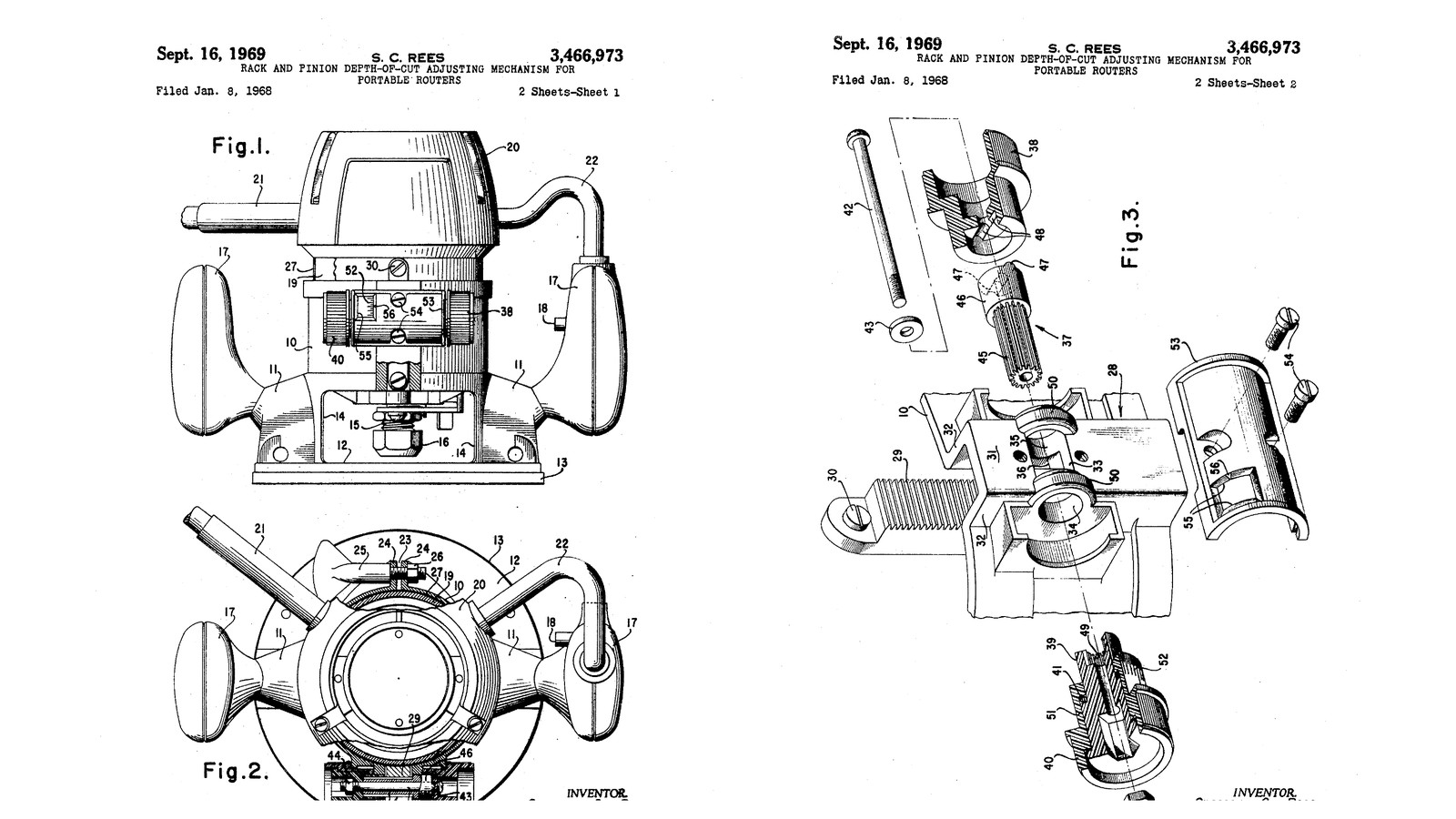

Rack-and-Pinion Router With a Zero-Set Knob: Two Knobs on One Hollow Pinion, Set to Zero on the Work (Rees, 1969)
Spencer C. Rees of Pickens, South Carolina, received US 3,466,973, dated 16 September 1969, for The Singer Company. A rack screwed to the motor housing is moved by a pinion through a window in a box on the base. The pinion is a hollow shaft running in one bore through the box's two side lugs, with a knob at each end. One knob turns it. The other, a zero-set knob with graduations, slips on its sleeve against an O-ring, so it can be set to zero with the bit touching the work. One screw through the middle holds it all together. Only the pinion shaft was metal; the rest was moulded.
We print every part in PETG round a small DC motor. The sizes are ours.
Продвинутый
About 3 days
Инструкции
1
1
What one turn of the knob does
What one turn of the knob does
Загрузка блокнота Jupyter…
2
2
Read US 3,466,973
Read US 3,466,973
"The zero-set knob 40 has a reduced diameter portion 51 which carries circumferentially-spaced graduation marks 52 on its surface." "In the above-described structure it will be noted that the only metallic part required is the pinion shaft 37 which is a relatively simple two-diameter piece."
3
3
Print the base
Print the base
The base 10: the split ring with clamp lugs, the box 28 for the rack with its two lugs 50 and stepped bore 33, the window 36, two legs 11 down to the plate 12 with its aperture, and two handle arms. Print it plate down. PETG, 0.2 mm layers, 40 % infill, 5 walls.
4
4
Print the motor housing
Print the motor housing
The housing 19: a tube for a 42 mm motor, 56 mm outside, a ledge with an 18 mm hole and two M4 holes, and two M3 holes for the rack. Print it ledge down. PETG, 0.2 mm layers, 40 % infill, 5 walls.
5
5
Print the small parts
Print the small parts
One plate: the rack 29 (module 1.5), the hollow pinion shaft 37 with its toothed (splined) part, bearing part and end ribs, the adjusting knob 38 with grooves, the flanged sleeve 39, the zero-set knob 40 with 20 graduations and an O-ring groove, and the cover plate 53 with its window 55 and mark 56. PETG, 0.2 mm layers, 40 % infill, 5 walls.
6
6
Motor in the housing
Motor in the housing
Fit the collet adapter on the motor's shaft, stand the motor in the housing on its ledge and screw it down with two M4 screws; wire it through a toggle switch to the DC supply. Screw the rack to the housing's front with two M3 screws.
Материалы для этого шага:
 Филамент PETG1 штука
 Электродвигатель1 штука
 Motor Shaft Collet Adapter1 штука
 Винт с цилиндрической головкой и внутренним шестигранником2 штук
 Машинные винты2 штук
 Тумблер1 штука
 Монтажный провод1 штука
 Термоусадочная трубка1 штука
Необходимые инструменты:
 3D-принтер FDM
 Источник питания постоянного тока
 Электрический паяльник
 Набор шестигранных ключей
 Набор отвёрток
 Гратосниматель
7
7
Base and handles
Base and handles
Turn two hardwood handles 17 and bolt one to each arm with an M8 bolt. Slide the housing into the base with the rack in the box's channel, and put an M5 screw with a wing nut through the clamp lugs.
Материалы для этого шага:
 Доска из твёрдой древесины1 штука
 Набор шестигранных болтов2 штук
 Шестигранная гайка3 штукВинт с цилиндрической головкой и внутренним шестигранником1 штука
 Гайка-барашек1 штука
Необходимые инструменты:
 Токарный станок по дереву
 Аккумуляторная дрель
 Набор свёрл
 Разводной ключ
8
8
Pinion, knobs and cover
Pinion, knobs and cover
Push the pinion shaft through the box's bore from the right, its toothed part through the window meshing with the rack, its bearing part in the right lug. Fit the O-ring in the zero-set knob's groove, push the sleeve into the knob, and slide them onto the shaft's toothed end from the left, the sleeve in the left lug. Fit the adjusting knob on the right end, its grooves on the shaft's ribs. Pass a long M4 screw through knob, shaft and sleeve with a washer, into a nut in the sleeve, and tighten it until the knobs have only a little end play. Screw the cover over the box with two M3 screws.
Материалы для этого шага:
 Уплотнительное кольцо круглого сечения1 штукаВинт с цилиндрической головкой и внутренним шестигранником1 штука
 Плоская шайба1 штукаШестигранная гайка1 штукаМашинные винты2 штук
Необходимые инструменты:
Набор шестигранных ключейНабор отвёрток9
9
Set zero and rout
Set zero and rout
Fit a bit. Loosen the clamp, turn the adjusting knob until the bit's tip touches the work, then turn the zero-set knob alone until its zero lines up with the cover's mark. Turn the adjusting knob to the depth wanted, read off the graduations, and clamp. Rout with both hands on the handles.
Необходимые инструменты:
 Набор фрезДоска из твёрдой древесины
 Струбцина с направляющей
 Цифровой штангенциркуль 6 дюймов
 Защитные очки
10
10
Troubleshooting
Troubleshooting
Rack and pinion router troubleshooting.
Flow
Loading...
11
11
History and honest limits
History and honest limits
**Spencer C. Rees** of Pickens, South Carolina, assignor to The Singer Company, US 3,466,973, dated 16 September 1969, filed 8 January 1968. He claimed a rack on the motor housing, "a pair of lugs formed on the base in fixed spaced relation on opposite sides of the rack and having aligned cylindrical apertures", a hollow pinion shaft, an adjusting knob, a flanged sleeve, "a zero-set knob frictionally coupled to said sleeve", and "single fastening means" through them all. His pinion shaft was metal and the rest moulded; ours is all printed. His motor ran on mains; ours is a small DC motor. He gives no sizes; every size here is ours.
Материалы
14- 1 штукаЗаполнитель
- 1 штукаЗаполнитель
- 1 штукаЗаполнитель
- Заполнитель
- 4 штукЗаполнитель
- Заполнитель
- Заполнитель
- 1 штукаЗаполнитель
- 1 штукаЗаполнитель
- Заполнитель
- 4 штукЗаполнитель
- 1 штукаЗаполнитель
- Заполнитель
- 1 штукаЗаполнитель
Требуемые инструменты
15- Заполнитель
- Заполнитель
- Заполнитель
- Заполнитель
- Заполнитель
- Заполнитель
- Заполнитель
- 1 vendor sell this, none ship to you yetЗаполнитель
- Заполнитель
- Заполнитель
- 1 vendor sell this, none ship to you yetЗаполнитель
- Заполнитель
- Заполнитель
- Заполнитель
- Заполнитель
Файлы дизайна
3По этому чертежу делают

Связанные чертежи
Эти чертежи делятся знаниями — техники, материалы или принципы
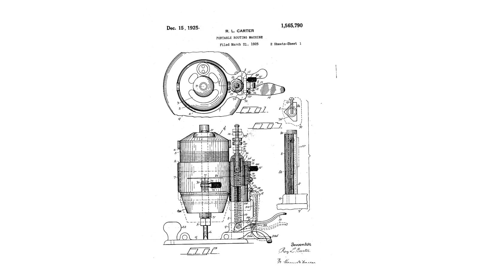
Rack-and-Pawl Plunge Router: The Motor Rides One Post on a Spring and Steps Down a Tooth at a Time (Carter, 1925)
от Forge
Деревообработка
0
0
0
0
0
0
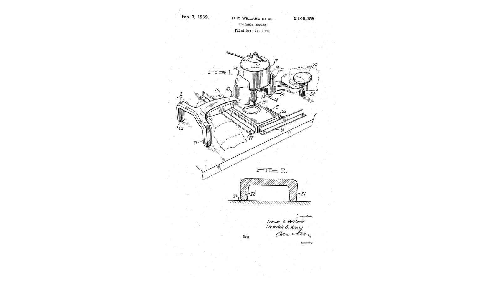
Three-Legged Router: A T-Frame on the Table Beside the Work, Its Depth Set by a Knob While Cutting (Willard & Young, 1939)
от Forge
Industry 3.0 — Assembly Line & Mass Production (1913)
0
0
0
0
0
0
CC0 Общественное достояние
Этот чертёж выпущен под лицензией CC0. Вы можете свободно копировать, изменять, распространять и использовать эту работу в любых целях без запроса разрешения.
Поддержите мейкера, покупая товары через его чертёж, где он получает Комиссию мейкера установленную продавцами, или создайте новую итерацию этого чертежа и включите его как связь в свой чертёж для распределения дохода.