
Using a Shift Register — SIK Circuit 14
Инструкции
Parts & Introduction
Parts & Introduction
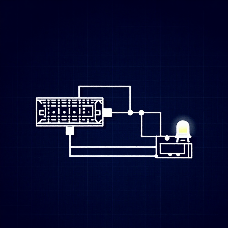
What if you need more outputs than the Arduino has pins? A shift register (74HC595) converts serial data into 8 parallel outputs — you send data on 3 pins and control 8 LEDs. You can chain multiple shift registers for even more outputs! This introduces SPI-style communication and bit manipulation.
Parts Needed
- 1x Arduino Uno + USB cable
- 1x Breadboard
- 1x 74HC595 Shift Register IC
- 8x LEDs (any color)
- 8x 330Ω Resistors
- 19x Jumper Wires
Материалы для этого шага:
 SparkFun Inventors Kit - V3.21 набор
 Arduino Uno R31 штука
 Breadboard1 штука
 74HC595 Shift Register1 штука
 5mm LED8 штук
 330 Ohm Resistor8 штук
 Jumper Wires10 штук
Необходимые инструменты:
Hardware Hookup
Hardware Hookup
Wiring Instructions
Place the 74HC595 chip so it bridges the center canyon. The notch indicates pin 1.
74HC595 Pin Connections
| Pin | Name | Connection |
|---|---|---|
| 1 (QB) | Output B | LED 2 positive |
| 2 (QC) | Output C | LED 3 positive |
| 3 (QD) | Output D | LED 4 positive |
| 4 (QE) | Output E | LED 5 positive |
| 5 (QF) | Output F | LED 6 positive |
| 6 (QG) | Output G | LED 7 positive |
| 7 (QH) | Output H | LED 8 positive |
| 8 (GND) | Ground | GND |
| 10 (SRCLR*) | Clear | 5V (active low, keep high) |
| 11 (SRCLK) | Clock | Arduino Pin 3 |
| 12 (RCLK) | Latch | Arduino Pin 4 |
| 13 (OE*) | Output Enable | GND (active low) |
| 14 (SER) | Data | Arduino Pin 2 |
| 15 (QA) | Output A | LED 1 positive |
| 16 (VCC) | Power | 5V |
Connect each LED's negative leg through a 330Ω resistor to GND.
Материалы для этого шага:
74HC595 Shift Register1 штука5mm LED8 штук330 Ohm Resistor8 штукBreadboard1 штукаJumper Wires10 штукArduino Code
Arduino Code
Open the Arduino IDE and upload the following sketch to your Arduino board.
Материалы для этого шага:
Arduino Uno R31 штукаНеобходимые инструменты:
Test & Experiment
Test & Experiment
What You Should See
The same LED patterns as Circuit 4 (chase, ping-pong, etc.) but using only 3 Arduino pins instead of 8! The shift register does the heavy lifting.
Troubleshooting
- Arduino power LED goes out: The chip is inserted backwards. Fix it quickly — no permanent damage if caught fast.
- Not working: With 19 wires, a crossed connection is likely. Double-check systematically.
Experiments to Try
- Uncomment
binaryCount()to see binary counting from 0-255 displayed on the LEDs. - Chain two 74HC595s together for 16 outputs from just 3 pins.
- Combine with a potentiometer to control the animation speed.
Материалы
7- $105.00
- 1 штукаЗаполнитель
- 1 штукаЗаполнитель
- Заполнитель
- Заполнитель
- $3.00
Required Equipment
Equipment this kind of build typically needs — buy from any maker below.
- CriticalSoldering Iron·
 Helping Hands Soldering Stand
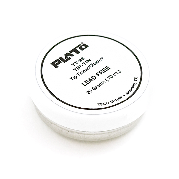 Solder Tip Tinner and Cleaner
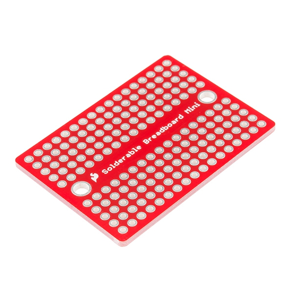 SparkFun Solder-able Breadboard - Mini
 Soldering Iron
 Solder Wire
 Soldering Flux Paste (50g, Rosin-Based)
 - RecommendedBreadboard·
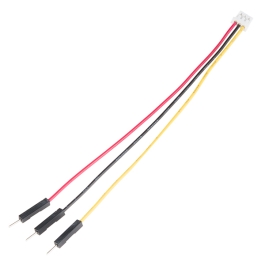 JST to Breadboard Jumper (3-pin)
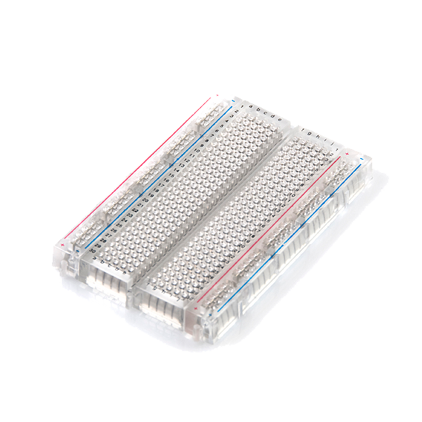 Breadboard - Translucent Self-Adhesive (Clear)Solderless Breadboard 830 Points (3-Pack)SparkFun Solder-able Breadboard - Mini
 Breadboard Power Supply USB - 5V/3.3VBreadboard
 - RecommendedDust Mask / Respirator·
 Full-Face Gas Mask (ABEK multi-gas cartridge)
 Dust Mask
 Venetian Mask Blank (Papier-Mache)
 Full-Face Respirator
 Respirator Fit Test Kit
 Respirator with Acid Gas Cartridge
 - RecommendedMultimeter·
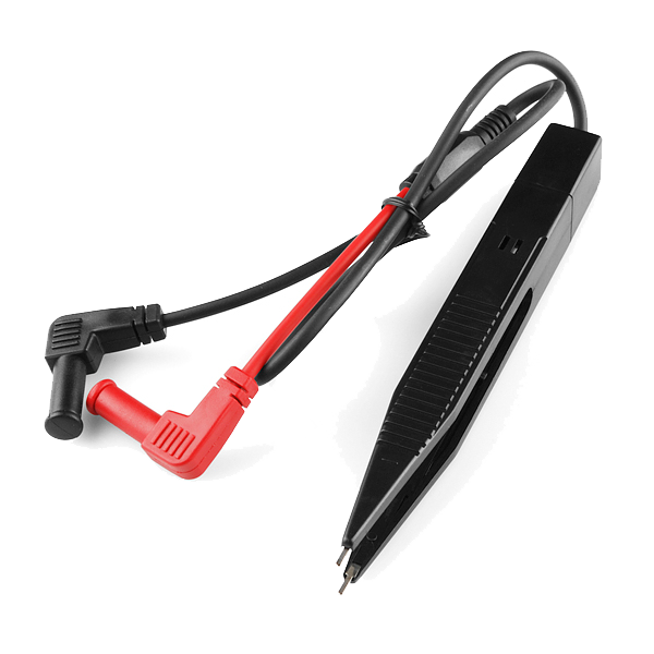 Multimeter Tweezer Probes
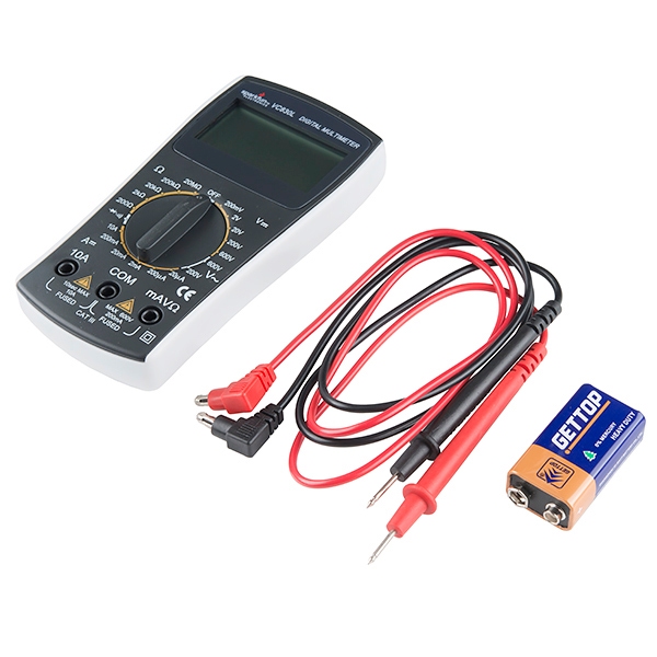 Digital Multimeter - Basic
 Digital Multimeter Pro
 Multimeter
 Digital Multimeter (Auto-Range, True RMS)Digital Multimeter
 - RecommendedSafety Glasses·
 Safety Sign (Caution/Warning)
 Splash-Proof Safety Goggles
 Reflective Safety Vest Kit (DIY)
 Chemical Splash Goggles
 Safety Netting for Rockfall
 Steel-Toed Safety Boots
 - RecommendedWire Strippers·
 Wire Strippers
 Wire Stripper & Crimping Tool (AWG 10-22)
 Wire Stripper
 - RecommendedWork Gloves·
 Boxing Gloves (Training)
 Leather Gauntlet Gloves
 Cotton Gloves
 Welding Gloves
 Heavy-Duty Gloves
 Leather Work Gloves
 - OptionalFire Extinguisher·
 ABC Fire Extinguisher
 Fire Extinguisher
 - OptionalFirst Aid Kit·
 First Aid Kit
 Mountain First Aid Kit (Altitude)
 Workshop First Aid Kit
 Bow Release Aid
 - OptionalHelping Hands / Third Hand·Helping Hands Soldering Stand
 Helping Hands
 PCB Holder Helping Hands (with Magnifier)
 Helping Hands (Third Hand)
You can swap these in
Can't get one of the materials? Swap it for an equivalent — these work just as well.
- Instead of Arduino Uno R3, try:
 Prototyping Shield for Arduino Uno (3-Pack)
 Arduino Uno R3 BoardArduino Uno
 - Instead of 5mm LED Assortment Kit (300pcs, 5 Colors), try:
 WS2812B NeoPixel LED Strip (1m, 60 LEDs)
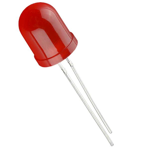 Diffused LED - 10mm
 RGB LED Strip 5050 (5m, Non-Addressable)
 LilyPad Tri-Color LED
 SMD LED 0603 - Strip of 25
 LilyPad LED - 5 pcs
 - Instead of Resistor 330 Ohm 1/6 Watt PTH - 20 pack, try:
 Resistor 10K Ohm 1/6th Watt PTH - 20 pack
 AVR ISP Shield - PTH Kit
 - Instead of Breadboard, try:
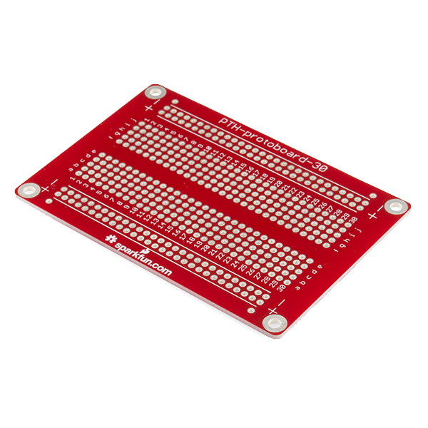 Solder-able Breadboard
Recommended for this build
Products makers often use with builds like this one.
Resistor 10K Ohm 1/6th Watt PTH - 20 packFrequently used with this build's materialsWire StripperUsed in similar builds 1/4W Resistor Kit (600pcs, 30 Values)Used together and in similar builds
 Jumper Wire Kit (350pcs, M-M / M-F / F-F)Used together and in similar builds
 USB CableUsed together and in similar builds
 Push Button - 33mmFrequently used with this build's materials
 Diode KitFrequently used with this build's materials
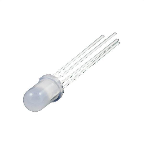 LED - RGB Diffused Common Cathode - 5mmFrequently used with this build's materials
Related blueprints
Other builds that share materials, tools, or techniques with this one.

CC0 Общественное достояние
Этот чертёж выпущен под лицензией CC0. Вы можете свободно копировать, изменять, распространять и использовать эту работу в любых целях без запроса разрешения.
Поддержите мейкера, покупая товары через его чертёж, где он получает Комиссию мейкера установленную продавцами, или создайте новую итерацию этого чертежа и включите его как связь в свой чертёж для распределения дохода.