ИСКУССТВО
КРАСОТА И ЗДОРОВЬЕ
РЕМЕСЛО
КУЛЬТУРА И ИСТОРИЯ
РАЗВЛЕЧЕНИЯ
ЭКОЛОГИЯ
ЕДА И НАПИТКИ
ОБРАТНАЯ ИНЖЕНЕРИЯ
НАУКИ
СПОРТ
ТЕХНОЛОГИИ
НОСИМЫЕ УСТРОЙСТВА


The Chip-on-Board Breakout: From a 0.4 mm Mezzanine to Pins You Can Reach
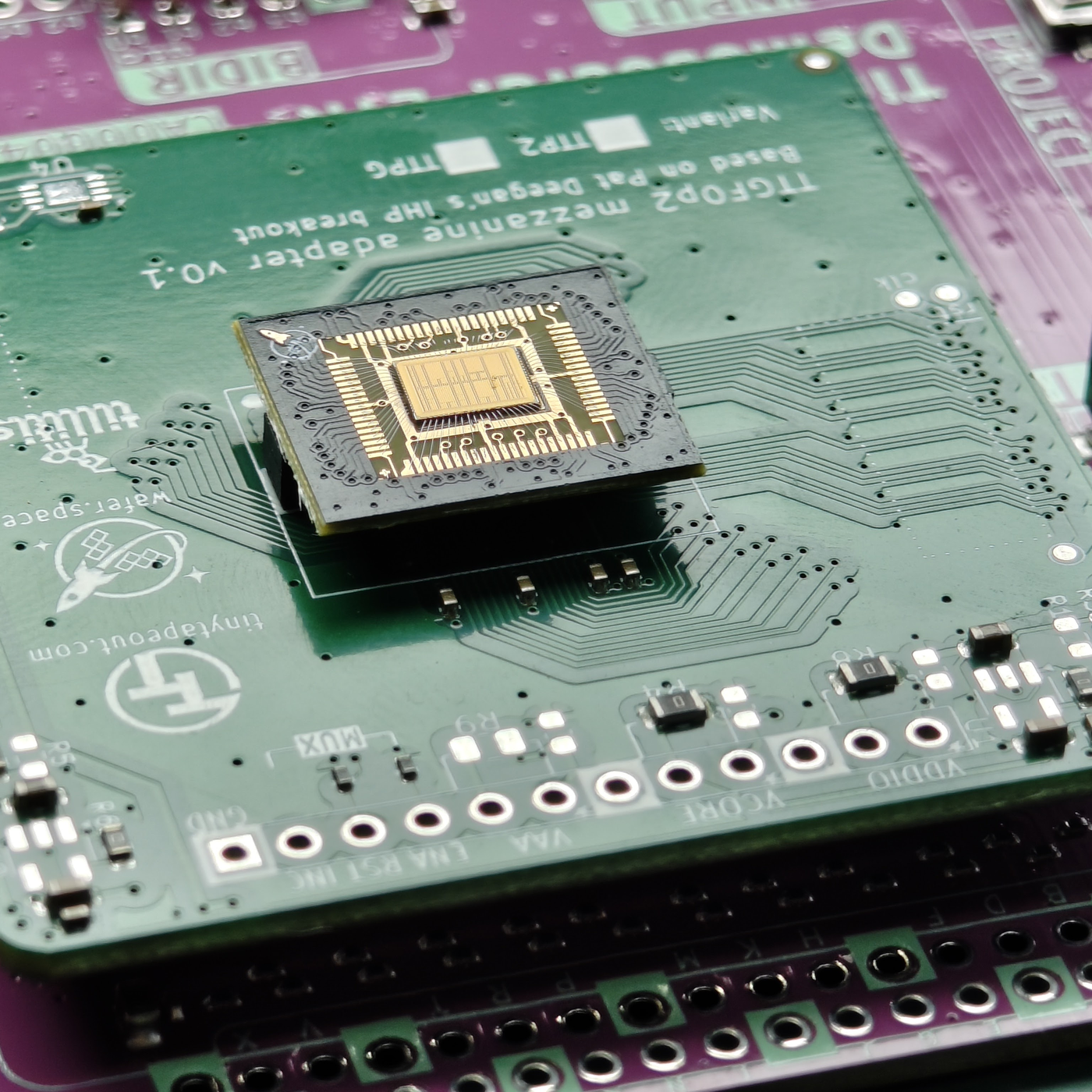
A chip from a shared wafer comes back tiny. On wafer.space's Run 1 it arrived as a chip-on-board part 14 × 16 mm, with the die wire-bonded under epoxy and a 70-pin mezzanine connector underneath at 0.4 mm pitch. Nothing on a bench can touch pins that small, so the first thing to build is a board that carries them back out.
wafer.space publishes example breakout motherboards in KiCad under Apache-2.0: one sheet, two boards. Each has the mating 70-pin mezzanine socket; one breaks the pins out to two 1 × 35 rows of 0.1-inch pin headers, the other to two rows of 35 castellated edge pads at 1 mm.
This rung works out why the fine pitch is needed and what spreading it out costs in board length, shows the published schematic, and builds the header version.
Продвинутый
About a day of soldering, plus board fabrication
Инструкции
1
1
Pitch against board edge
Pitch against board edge
Загрузка блокнота Jupyter…
2
2
Where the chip comes from
Where the chip comes from
The embedded blueprint designs the chip and orders it. This rung builds the board it plugs into.
3
3
What the chip-on-board plugs into
What the chip-on-board plugs into
From wafer.space's Run 1 documentation: the full-slot chip-on-board is 14 × 16 mm; the die's 74 bond pads follow the Tiny Tapeout convention, and all grounds are tied together on the default breakout. It carries a 70-pin, 0.4 mm pitch mezzanine connector (LCSC C19089236; the mating part is LCSC C19089262).
So that every project fits the same boards, the default breakouts share the same wire-bonding layout, the same 14 × 16 mm footprint and the same connector position; traces, signal types and net assignments are left to the designer. wafer.space notes that pinouts, connectors and footprints are specific to each run.
4
4
The published breakout schematic
The published breakout schematic
wafer.space's example motherboards, from the chip-on-board-wire-bonded-pcbs repository (run-1/motherboards, Apache-2.0), shown as published. On the left, the ".1\" Header" board: the mezzanine socket J102 (HCTL HC-PBB40C-70DP-0.4V-02, 70 pins at 0.4 mm) broken out to the 1 × 35 pin headers J101 and J103 at 2.54 mm. On the right, the "Castellated" board: the same socket J105 broken out to the 1 × 35 castellated edges J104 and J106 at 1 mm, so the whole breakout can itself be soldered onto a larger board.
Загрузка просмотрщика KiCanvas...
Профессиональный просмотрщик PCB-дизайна
5
5
Build the header board
Build the header board
Download the run-1/motherboards project from the repository and open it in KiCad. The files are saved by KiCad 10, so an older KiCad will not open them. Plot the Gerber and drill files and order the board from a PCB fabricator, with a solder-paste stencil for the mezzanine footprint.
Hold the stencil over the mezzanine pads and spread lead-free solder paste across it in one stroke. Place the socket with fine tweezers, square to its pads, and reflow it with the hot-air station until the paste flows and settles. Inspect every one of the 70 joints with the loupe; clear any bridge between neighbouring pins with flux and the iron or hot air.
Solder the two 1 × 35 pin headers with the iron. Before you plug in a chip, check with the multimeter that no two neighbouring header pins are shorted, and that each header pin reaches the socket pin the schematic connects it to.
Материалы для этого шага:
 Печатная плата1 штука
 Межплатный разъём1 штука
 Штыревая линейка2 штук
 Паяльная паста (бессвинцовая)1 штука
 Оловянно-свинцовый припой1 штука
 Флюс1 штука
Необходимые инструменты:
 Термовоздушная паяльная станция
 Паяльник
 Пинцет с острыми губками
 Ювелирная лупа
 Мультиметр
 Настольный компьютер
6
6
A breakout that shorts or does not connect
A breakout that shorts or does not connect
Breakout board troubleshooting.
Flow
Loading...
7
7
Sources and honest limits
Sources and honest limits
**Sources**, read 29 September 2026: wafer.space's chip-on-board-wire-bonded-pcbs repository (README, run-1/README and run-1/motherboards, Apache-2.0). The schematic in step 4 is theirs, unchanged. The photograph is theirs too, from the same repository: a Run 1 chip-on-board seated on a Tiny Tapeout mezzanine adapter board (TTGF02, v0.1), not the header board built in step 5.
**Honest limits.** This rung has not been built for this blueprint; the soldering steps are standard practice for a 0.4 mm surface-mount connector, not wafer.space instructions. The pinout and footprint are Run 1's, and wafer.space says they are expected to change in later runs, so check the current run's documentation before ordering boards.
Материалы
6- 1 штукаЗаполнитель
- 1 штукаЗаполнитель
- Заполнитель
- Заполнитель
- 1 штукаЗаполнитель
- 1 штукаЗаполнитель
Требуемые инструменты
6- Заполнитель
- 2 vendors sell this, none ship to you yetЗаполнитель
- Заполнитель
- Заполнитель
- Заполнитель
- Заполнитель
Связанные чертежи
Эти чертежи делятся знаниями — техники, материалы или принципы


CC0 Общественное достояние
Этот чертёж выпущен под лицензией CC0. Вы можете свободно копировать, изменять, распространять и использовать эту работу в любых целях без запроса разрешения.
Поддержите мейкера, покупая товары через его чертёж, где он получает Комиссию мейкера установленную продавцами, или создайте новую итерацию этого чертежа и включите его как связь в свой чертёж для распределения дохода.