ИСКУССТВО
КРАСОТА И ЗДОРОВЬЕ
РЕМЕСЛО
КУЛЬТУРА И ИСТОРИЯ
РАЗВЛЕЧЕНИЯ
ЭКОЛОГИЯ
ЕДА И НАПИТКИ
ОБРАТНАЯ ИНЖЕНЕРИЯ
НАУКИ
СПОРТ
ТЕХНОЛОГИИ
НОСИМЫЕ УСТРОЙСТВА
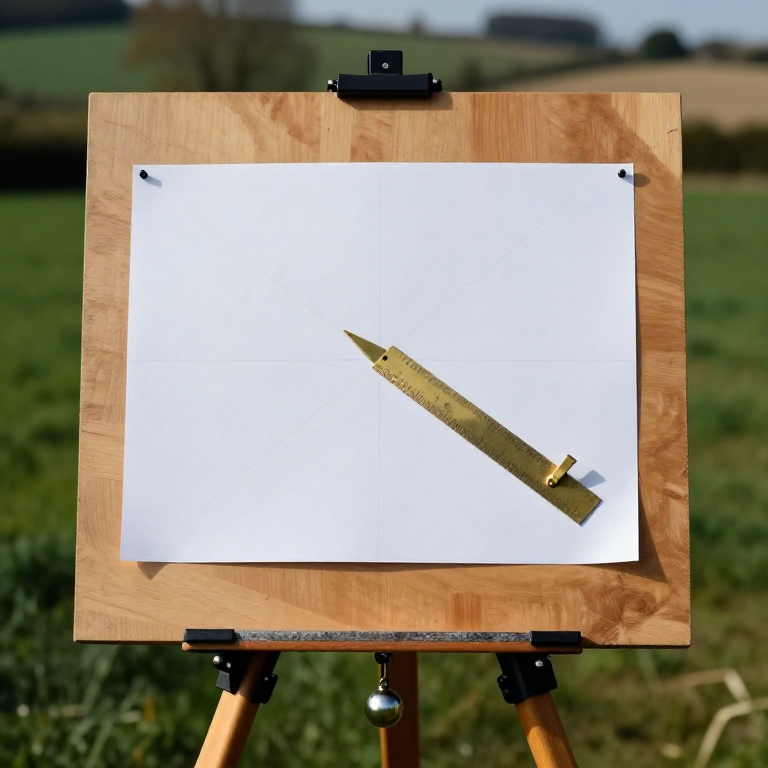


The Plane Table: Mapping by Drawing on Site
Every other surveying method records numbers in a book and turns them into a drawing later, at a desk, where a transcription error cannot be caught. The plane table skips the numbers entirely: the map is drawn ON SITE, at scale, with the ground in front of you.
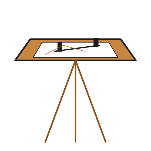
A board is levelled on a tripod and oriented so that north on the paper points north on the ground. Sight a feature along a straight edge, draw a ray, move to a second known station, sight the same feature again, and where the two rays cross is the feature's position — no angles measured, no trigonometry, no arithmetic at all.
It dominated topographic mapping from the sixteenth century until the aeroplane, and its real advantage is still unbeaten: you can see immediately whether your map looks like the place you are standing in.
Средний
1 day
Инструкции
1
1
Make the board and the alidade
Make the board and the alidade
Mount a flat, stable board on a tripod so it can be levelled and rotated, then locked. The alidade is simply a straightedge with a sight at each end — a ruler with two upright pins, or a card sight and a slit.
The one property that matters is that the line of sight must be exactly parallel to the drawing edge, and directly above it. If the sight line sits a centimetre to one side of the edge you draw against, every ray on your map is displaced by that centimetre at map scale — a systematic error that no amount of care in the field will reveal.
Материалы для этого шага:
 Картон6 штук
 Брус из дугласовой пихты1 length
Необходимые инструменты:
 Фотоштатив
 Ножовка по дереву
 Линейка
2
2
Set up over a known point and orient the board
Set up over a known point and orient the board
Level the board, and use a plumb bob to bring the point on your paper that represents your station exactly over the peg on the ground. Then rotate the whole board until a drawn reference line points at a known feature, and lock it.
Centring and orienting are separate operations and both matter. Orienting by compass is quick and good to perhaps a degree; orienting by sighting a distant known point is far better and costs nothing extra. Once locked, the board must not move — knocking the tripod invalidates every ray you have drawn from that station.
Материалы для этого шага:
 Деревянные нагели6 штук
Необходимые инструменты:
 Отвес
Отвес Строительный уровень
 Компас
3
3
Draw rays, do not measure angles
Draw rays, do not measure angles
Put the alidade edge on your station point, swing it until the sights line up with the feature, and draw a light ray. Label it. Repeat for every feature visible from here.
You have recorded a direction without ever knowing what it was in degrees, which is the point — there is no angle to write down wrongly, no protractor to misread, and no plotting step later. Keep the rays LIGHT: a finished plane-table sheet is covered in construction lines and the map has to be readable through them.
Материалы для этого шага:
 Миллиметровая бумага10 штук
Необходимые инструменты:
Линейка4
4
Measure the baseline once, and plot it to scale
Measure the baseline once, and plot it to scale
Move to a second station, measure the distance between the two stations carefully, and plot that one line to your chosen scale.
This is the only distance in the whole survey you have to measure, and every dimension on the finished map derives from it — so measure it twice, by different people if you can. Make it long and roughly perpendicular to the direction of most of your detail: a short baseline makes the ray intersections shallow and the positions uncertain, which the notebook quantifies.
Необходимые инструменты:
 Рулетка
5
5
Intersect, and check with a third station
Intersect, and check with a third station
From the second station, re-sight every feature. Each new ray crosses its partner from the first station, and the crossing is the feature's position.
Now take a third station and sight the same features again. Three rays should meet at a point; in practice they form a small triangle — the 'triangle of error'. Its SIZE is your accuracy, measured rather than claimed, and a large one tells you which station or which sighting to redo. Two rays can never reveal a mistake; three always can.
Необходимые инструменты:
Линейка6
6
Why the baseline and the angle of cut decide everything
Why the baseline and the angle of cut decide everything
Загрузка блокнота Jupyter…
Необходимые инструменты:
Линейка7
7
Finish the map before you leave the site
Finish the map before you leave the site
Ink or firm up the features, add the scale bar, the north arrow, the date and who surveyed it, while you are still standing there.
The whole advantage of this method is that the ground is available to check against, and it stops being available the moment you walk away. A sheet of unlabelled construction rays taken home is worth far less than a rough but finished map — and a map without a scale bar and a date is not a map, it is a drawing.
Необходимые инструменты:
ЛинейкаМатериалы
4- 6 штукЗаполнитель
- 1 lengthЗаполнитель
- 6 штукЗаполнитель
- 10 штукЗаполнитель
По этому чертежу делают
Связанные чертежи
Эти чертежи делятся знаниями — техники, материалы или принципы



CC0 Общественное достояние
Этот чертёж выпущен под лицензией CC0. Вы можете свободно копировать, изменять, распространять и использовать эту работу в любых целях без запроса разрешения.
Поддержите мейкера, покупая товары через его чертёж, где он получает Комиссию мейкера установленную продавцами, или создайте новую итерацию этого чертежа и включите его как связь в свой чертёж для распределения дохода.