
Сотрудничество
ИСКУССТВО
КРАСОТА И ЗДОРОВЬЕ
РЕМЕСЛО
КУЛЬТУРА И ИСТОРИЯ
РАЗВЛЕЧЕНИЯ
ЭКОЛОГИЯ
ЕДА И НАПИТКИ
ОБРАТНАЯ ИНЖЕНЕРИЯ
НАУКИ
СПОРТ
ТЕХНОЛОГИИ
НОСИМЫЕ УСТРОЙСТВА
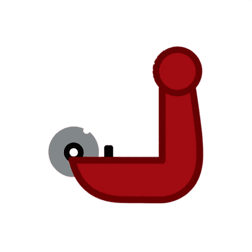
Sprung-Leg Tubing Cutter: a Bent Rod With a Disk Outside and a Roller Inside, the Handle's Screw Bends One Leg In (Zeiler, 1958)
Forge

Создано

Forge

13. ноябрь 2026NO
0
0
0
0
0

Sprung-Leg Tubing Cutter: a Bent Rod With a Disk Outside and a Roller Inside, the Handle's Screw Bends One Leg In (Zeiler, 1958)

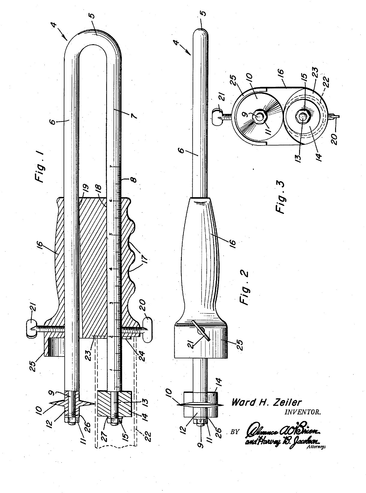
Ward H. Zeiler of Holyoke, Colorado, received US 2,821,781, dated 4 February 1958, for a plumber's tubing cutter that cuts a tube square, to length, near its end. The frame is one springy rod bent into a U. The lower leg goes into the tube and carries a roller. The upper leg carries a cutting disk outside the tube. A handle slides along both legs. Its front end stops against the tube end, so the cut length is read off a scale on the lower leg. A screw in the handle bends the upper leg in and presses the disk onto the tube, and turning the tool cuts it off. All sizes are ours.
Средний
About 2 days

Инструкции

1

Why the frame must spring

Загрузка блокнота Jupyter…
2

Read US 2,821,781

"The leg 7 is then inserted in the tube 22 and the roller 14 and the projection 24 are engaged in the upper portion of said tube. The screw 21 is then tightened for bending the leg 6 of the frame 4, thus engaging the knife 10 with the periphery of the tube 22."
3

Print the template

The bent frame, its ends, the disk, roller and handle at 1:1, with the oval bore, the screws and the scale. print at 100 % (check the 50 mm bar).
Файл дизайнаPDFCC0 - Free
4

Bend the frame

Cut 470 mm of 6 mm spring steel wire. Heat the middle 40 mm red with the torch and bend it round a 10 mm bar into a U with the legs 16 mm apart, and straighten the legs parallel. Heat the last 25 mm of each leg red and let it cool slowly in the dying forge, so the ends are soft enough to file and thread. Leave the rest of the legs as they are: they must spring.

Материалы для этого шага:

Пружинная стальная проволокаПружинная стальная проволока1 штука

Необходимые инструменты:
Горелка для пайки твёрдым припоемГорелка для пайки твёрдым припоем
ГорнГорн
Кузнечные клещиКузнечные клещи
Слесарные тискиСлесарные тиски
Слесарный молоток с шаровым бойкомСлесарный молоток с шаровым бойком
Ножовка по металлуНожовка по металлу
Сварочные перчаткиСварочные перчатки
Защитные очкиЗащитные очки
5

Thread the leg ends

Turn or file the last 24 mm of each leg to 5 mm, leaving a square shoulder, and cut an M5 thread on the last 8 mm with the die.

Необходимые инструменты:

Токарный станок по металлуТокарный станок по металлу
Трёхкулачковый токарный патронТрёхкулачковый токарный патрон
Токарный резецТокарный резец
Набор напильниковНабор напильников
Набор метчиков и плашекНабор метчиков и плашек
Цифровой штангенциркуль 6 дюймовЦифровой штангенциркуль 6 дюймов
Смазочно-охлаждающее маслоСмазочно-охлаждающее масло
6

Turn the disk and the roller

Disk: chuck a tool steel bar, turn 12 mm of it to 18 mm, drill it 5 mm, and turn the front 6 mm to a 50 degree edge, sharp in its middle. Turn the next 4 mm down to a 10 mm hub and part it off. Roller: turn 10 mm mild steel bar 16 mm long and drill it 5.2 mm, so it spins freely on the leg.

Материалы для этого шага:

Пруток инструментальной сталиПруток инструментальной стали1 штука
Круглый пруток из малоуглеродистой сталиКруглый пруток из малоуглеродистой стали1 штука

Необходимые инструменты:

Токарный станок по металлуТокарный станок по металлу
Трёхкулачковый токарный патронТрёхкулачковый токарный патрон
Токарный резецТокарный резец
Отрезной резецОтрезной резец
Набор центровочных свёрлНабор центровочных свёрл
Набор свёрлНабор свёрл
Цифровой штангенциркуль 6 дюймовЦифровой штангенциркуль 6 дюймов
Защитные очкиЗащитные очки
7

Harden and temper

Heat the disk to a cherry red, until a magnet no longer sticks, and quench it in water, moving it about. Rub it bright with a stone, warm it on a piece of steel plate over the fire, and quench again as soon as it turns a light straw colour.

Необходимые инструменты:

ГорнГорн
Кузнечные клещиКузнечные клещи
Небольшой магнитНебольшой магнит
Закалочная бадьяЗакалочная бадья
ВодаВода
Точильный каменьТочильный камень
Сварочные перчаткиСварочные перчатки
Защитные очкиЗащитные очки
8

Make the handle

Saw 90 mm of 32 mm aluminium bar and face the ends. Drill two 6.2 mm holes through it lengthways, 16 mm apart, each 8 mm off the centre. With a round file, open the front 70 mm of the upper hole towards the lower one, 1.8 mm at the front face, tapering to nothing. Drill and tap M6 into the upper hole from the top, 12 mm from the front, and into the lower hole from below, 14 mm from the front. Saw and file away the lower half of the front 8 mm, leaving a 10 mm round boss round the lower hole. File three finger grooves underneath.

Материалы для этого шага:

Круглый алюминиевый прутокКруглый алюминиевый пруток1 штука

Необходимые инструменты:

Ножовка по металлуНожовка по металлу
Токарный станок по металлуТокарный станок по металлу
Трёхкулачковый токарный патронТрёхкулачковый токарный патрон
Сверлильный станокСверлильный станок
Машинные тискиМашинные тиски
Набор свёрлНабор свёрл
Набор метчиков и плашекНабор метчиков и плашек
Набор напильниковНабор напильников
Набор надфилейНабор надфилей
Цифровой штангенциркуль 6 дюймовЦифровой штангенциркуль 6 дюймов
9

Make the guard

Cut a strip of brass sheet 12 mm wide and 50 mm long, bend it into a half round hood that reaches 12 mm past the handle's front over the disk, and fix its back end on top of the handle with two small screws.

Материалы для этого шага:

Латунный листЛатунный лист1 штука
Винт с цилиндрической головкой и внутренним шестигранникомВинт с цилиндрической головкой и внутренним шестигранником2 штук

Необходимые инструменты:

Ножовка по металлуНожовка по металлу
Набор напильниковНабор напильников
Сверлильный станокСверлильный станок
Набор свёрлНабор свёрл
Набор метчиков и плашекНабор метчиков и плашек
Слесарные тискиСлесарные тиски
10

Assemble

Slide the handle onto the legs from the open end, the upper leg in the oval bore. Put the disk on the upper leg's end, hub outwards, then a washer and an M5 nut, snug enough that the disk still turns. Fit the roller the same way on the lower leg. Screw in the M6 feed screw on top and the setscrew below.

Материалы для этого шага:

Плоская шайбаПлоская шайба2 штук
Шестигранная гайкаШестигранная гайка2 штук
Винт с цилиндрической головкой и внутренним шестигранникомВинт с цилиндрической головкой и внутренним шестигранником1 штука
Установочный винт с чашеобразным концомУстановочный винт с чашеобразным концом1 штука

Необходимые инструменты:

Разводной ключРазводной ключ
Набор шестигранных ключейНабор шестигранных ключей
11

Mark the scale

Slide the handle so its recess face is 20 mm from the disk's edge and lock it. File a nick across the lower leg at the handle's back face and mark it 20. File a nick every 10 mm towards the bend, deeper every 50 mm. The handle's back face now reads the cut length.

Необходимые инструменты:

Набор надфилейНабор надфилей
Цифровой штангенциркуль 6 дюймовЦифровой штангенциркуль 6 дюймов
12

Cut a tube to length

Set the handle to the length you want and lock the setscrew. Push the lower leg into the tube until the end bears in the recess, with the roller and boss against the inside. Tighten the feed screw until the disk touches. Turn the tool round the tube, giving the screw a little more each turn, until the end drops off. Clean the cut with a deburring tool.

Материалы для этого шага:

Медная трубаМедная труба1 штука

Необходимые инструменты:

Слесарные тискиСлесарные тиски

ГратоснимательГратосниматель
Набор шестигранных ключейНабор шестигранных ключей
Цифровой штангенциркуль 6 дюймовЦифровой штангенциркуль 6 дюймов
13

Troubleshooting

Sprung-leg tubing cutter troubleshooting.

Flow

Loading...
14

History and honest limits

**Ward H. Zeiler** of Holyoke, Colorado, US 2,821,781, dated 4 February 1958, filed 23 November 1956. He claimed "a substantially U-shaped resilient frame including legs extending slidably through the bores" and "a feed screw ... for bending said one leg within the confines of the handle for engaging the cutting disk with the tube". His frame was "suitable resilient metal"; ours is spring steel wire. His handle was a metal sleeve with a guard formed on it; ours is aluminium bar with a brass guard. The patent gives no sizes; all of ours are ours.

Материалы

10

Требуемые инструменты

28

Файлы дизайна

1

По этому чертежу делают

CC0 Общественное достояние

Этот чертёж выпущен под лицензией CC0. Вы можете свободно копировать, изменять, распространять и использовать эту работу в любых целях без запроса разрешения.

Поддержите мейкера, покупая товары через его чертёж, где он получает Комиссию мейкера установленную продавцами, или создайте новую итерацию этого чертежа и включите его как связь в свой чертёж для распределения дохода.

Обсуждение

(0)

Войти чтобы присоединиться к обсуждению

Загрузка комментариев...