UBUHANZI
UBWIZA N'UBUZIMA
UBUKORIKORI
UMUCO N'AMATEKA
IMYIDAGADURO
IBIDUKIKIJE
IBIRIBWA N'IBINYOBWA
UBWUBATSI BUSUBIRA INYUMA
UBUMENYI
SIPORO
IKORANABUHANGA
IBYAMBARWA
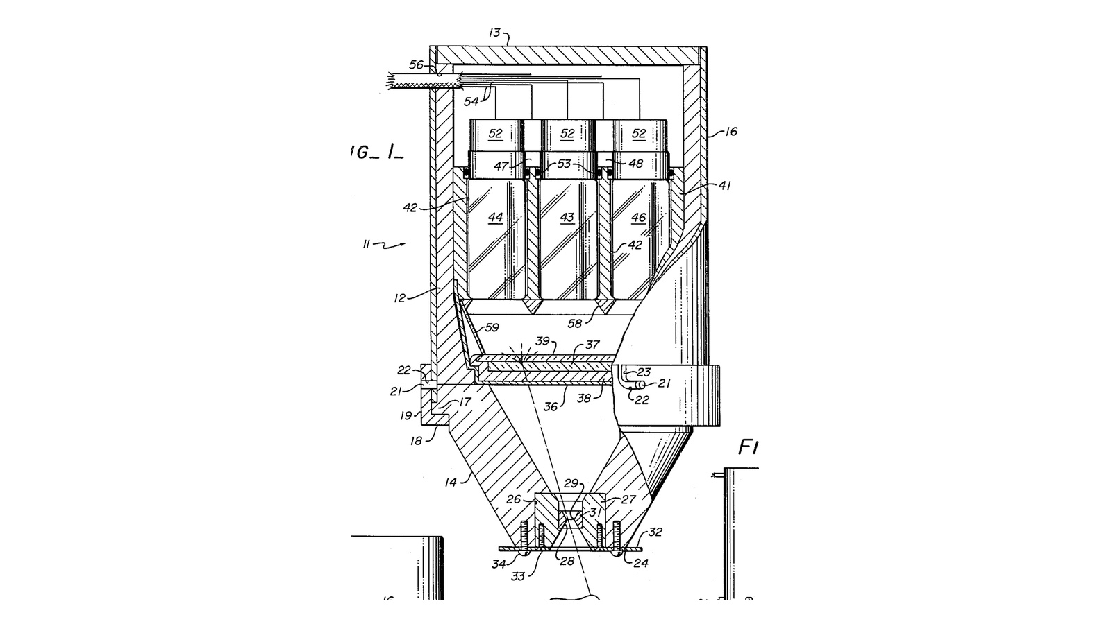


Anger Scintillation Camera
Every blueprint before this one in the batch shines something through the patient from outside. This one turns that inside out: **the source is swallowed or injected, and the patient becomes the thing that is glowing.**
That changes what an image even means. An X-ray shows you where tissue is DENSE. A gamma camera shows you where a molecule WENT - to bone that is remodelling, to a thyroid that is taking up iodine, to a tumour that is consuming sugar. It is the first functional image in this chain rather than an anatomical one.
**US 3,011,057**, "Radiation image device", Hal O. Anger, filed 2. January 1958 and granted 28. November 1961. Anger's problem was that a scintillator flashes when a gamma ray is absorbed, but the flash does not say where. His answer needs no lens at all: **view one large crystal with several photomultipliers at once, and compute the position from how much light each one received.** The patent puts it plainly - "each phototube gauges the remoteness of the scintillation by measuring the amount of light received. The electrical signals from the phototubes are compared in a computing circuit, which reports the precise location of each scintillation." Seven tubes, hexagonally arranged, over a planar sheet of sodium iodide.
It is a weighted average, and that is genuinely all it is. Sixty-five years later every gamma camera in every hospital still computes position exactly this way, and the arithmetic is called Anger logic.
**You will build it with light and photodiodes**, which lets you do the real thing rather than a cartoon of it: a diffuser sheet, four detectors underneath at known positions, a small bright spot on top, and a computed position you can check against a ruler. Then you will measure the two things that actually limit it - counting statistics, and the collimator that throws away over ninety-nine per cent of everything the patient emits.
Hagati
3 hours
Amabwiriza
1
1
The detector plane: four sensors, a diffuser, and one number each
The detector plane: four sensors, a diffuser, and one number each
Mount four photodiodes on a board at the corners of a 100 mm square, facing upward, and write their coordinates down - those exact numbers go into the arithmetic later.
Above them, at about 20 mm, fit a sheet of translucent diffuser: white acrylic, or several layers of vellum. This stands in for the scintillator crystal and light guide, and **its thickness is the single most important choice in the build.**
Too thin and a spot of light directly over one photodiode is seen only by that one, with the others reading nothing - there is no gradient, so there is nothing to interpolate and the camera can only tell you which quadrant. Too thick and every detector sees an almost identical amount wherever the spot is, and the computed position collapses toward the centre.
You want the middle: each detector's reading should vary smoothly and substantially as the spot moves. Expect to try two or three thicknesses. Anger faced exactly this and solved it with a light guide of carefully chosen geometry - visible in the patent drawing as the tapered block between crystal and tubes.
Ibikoresho by'iyi ntambwe:
 Fotodiyodi (BPW34)4 ibice
 Urupapuro rwa Akiriliki2 ibice
 Urupapuro rubonerana4 impapuro
 Urubaho rufite utwobo / urubaho rw'igerageza1 igice
Ibikoresho bikenewe:
 Ahantu ho Gushongesha
 Ikigereranyo cya Digitale cy'Amasentimetero 6
 Icyuma cy'Ubukorikori
 Umurongo w'ipima
2
2
Read four channels honestly
Read four channels honestly
Each photodiode feeds a transimpedance amplifier - an op-amp with a resistor in the feedback path - and then a microcontroller analogue input. Four identical channels.
**Identical is the word that matters.** Anger logic is a comparison between channels, so any difference in gain between them is read as a difference in position. Use resistors from the same batch, the same op-amp type throughout, and calibrate before you trust anything: put the light spot at the exact centre and adjust each channel's software gain until all four report the same value.
Also measure and subtract the dark reading of each channel with the light off. A constant offset on one channel drags every computed position toward it, and it is the most common reason a working rig reports a persistent bias.
Print the four raw numbers continuously. You should be able to move the spot by hand and watch them trade off against each other before you compute anything at all.
Ibikoresho by'iyi ntambwe:
 Sirikwi ya amplifikateri y'imikorere4 ibice
 Ikusanyirizo ry'Ibirwanya Amashanyarazi1 igice
 Arduino Uno R31 igice
 Ikibaho cy'Ibizamini1 igice
 Insinga zo guhuza20 ibice
Ibikoresho bikenewe:
Ahantu ho Gushongesha Igipimo cya Digitale cy'Urwego rw'Ubushakashatsi
 Osilosikopu
 Mudasobwa yo ku Meza
3
3
The sketch: four channels in, one position out
The sketch: four channels in, one position out
Flash this and the rig is a camera. It calibrates itself in two prompts - dark first, then a spot at the exact centre - and thereafter prints a position and the four channel values that produced it, so you can always see WHY it answered what it did.
The Anger logic is four lines in the middle and is marked as such. Everything around it exists to make the four numbers comparable, which is the part that decides whether the position is right: dark subtraction, channel equalisation and 32-sample averaging. A gain difference between two detectors is not read as a gain difference - it is read as the spot being closer to one of them.
Put the detector coordinates in DET_X and DET_Y from your own measurements. Those numbers go directly into the answer, so measure the board rather than trusting that your square came out square.
anger_logic.inocpp
Ibikoresho bikenewe:
Mudasobwa yo ku Meza Umugozi wa USB-B
4
4
Anger logic, and check it against a ruler
Anger logic, and check it against a ruler
Compute the signal-weighted mean of the detector positions:
**x = (Σ signal × x-position) ÷ (Σ signal)**, and the same for y.
That is the entire algorithm. No lens, no focusing, no reconstruction - a weighted average of four numbers.
Now test it properly. Draw a grid on the diffuser at 10 mm spacing, put the light spot on each intersection in turn, and record the computed position beside the true one. Twenty-five points takes ten minutes and gives you a real characterisation.
Plot computed against true for both axes. In the middle it should be close to a straight line. Toward the edges it will bend - the computed values compress inward, because a weighted mean of four fixed points can never land outside the square they define. **That is not a bug in your build; it is a property of the method**, and real gamma cameras carry a stored correction table for exactly this, measured the same way you just did.
Ibikoresho bikenewe:
Mudasobwa yo ku MezaUmurongo w'ipima Itara rya LED ryo kugenzura
5
5
Make it dimmer, and watch the position get noisy
Make it dimmer, and watch the position get noisy
This is the measurement that explains why nuclear medicine images look the way they do.
Put the spot at one fixed position and record the computed position two hundred times. Compute the standard deviation. Then dim the light - a neutral density filter, or simply reduce the LED current - and repeat, at four or five brightness levels, measuring the total signal each time.
Plot the position spread against the total signal. You should find that the scatter shrinks as the square root of the light collected: to halve the blur you must gather four times as much.
**That single relationship is why a bone scan is blurry.** A gamma camera resolves 6 to 12 millimetres at best - not because the electronics are poor, but because each event is located from a modest number of light photons, and you cannot buy precision without collecting more of them. Collecting more means more radioactivity in the patient or a longer scan, and both have hard limits.
Every other blueprint in this batch is limited by geometry or by materials. This one is limited by counting, and no engineering removes it.
Ibikoresho by'iyi ntambwe:
 Akayunguruzo k'ubwinshi buringaniye1 igice
Ibikoresho bikenewe:
Mudasobwa yo ku MezaIgipimo cya Digitale cy'Urwego rw'Ubushakashatsi6
6
The weighted mean, the noise, and the lead
The weighted mean, the noise, and the lead
Gupakira ikaye ya Jupyter…
7
7
When the position is wrong
When the position is wrong
The first two questions are both about the diffuser, from opposite directions. The third is not a fault at all.
Flow
Loading...
8
8
Compendium: the collimator bargain, and how PET refuses it
Compendium: the collimator bargain, and how PET refuses it
**Why there has to be a slab of lead in front.** The crystal records that a gamma ray arrived, not the direction it came from. Without a collimator every point in the patient would contribute to every point in the image and you would get a uniform glow. So a lead plate 25 to 55 mm thick, drilled with thousands of parallel holes, absorbs everything not travelling nearly straight - **over ninety nine per cent of what leaves the patient, deliberately thrown away.**
**And the trade inside the trade.** Longer, narrower holes accept a narrower cone, so the picture is sharper - and less gets through, so the picture is noisier. Resolution and sensitivity are directly opposed and a department keeps several collimators to choose between them per study. It is the same shape of bargain as the grid ratio in blueprint two and the screen thickness in blueprint one: this batch keeps arriving at the same wall from different directions.
**SPECT** is this camera on a gantry, rotating around the patient and taking views from many angles, then reconstructing a three-dimensional distribution - tomography applied to an internal source, using the same maths as the blueprint after next.
**PET refuses the bargain entirely.** A positron annihilates and emits TWO photons in exactly opposite directions. Detect both, and the line between the two detectors that fired IS the direction - no lead needed, nothing thrown away for geometry. That is why PET is far more sensitive than SPECT, and why it needs a ring of detectors and fast coincidence timing rather than a collimator.
**A note on what this made possible.** Because the tracer follows a molecule rather than an anatomy, the picture answers a different kind of question: not "what shape is it" but "what is it doing". A tumour and scar tissue can look identical on CT and completely different on a functional scan. That is why modern practice bolts the two together in one machine - PET/CT - and shows you the function laid over the anatomy.
Ibikoresho
10- 4 ibiceUmwanya
- 2 ibiceUmwanya
- 4 impapuroUmwanya
- Umwanya
- Umwanya
- Umwanya
- Umwanya
- Umwanya
- Umwanya
- Umwanya
Ibikoresho bikenewe
9- Umwanya
- Umwanya
- Umwanya
- Umwanya
- Umwanya
- 1 vendor sell this, none ship to you yetUmwanya
- Umwanya
Blueprint zijyanye
Izi blueprint zisangira ubumenyi — uburyo, ibikoresho cyangwa amahame

CC0 Umurenge rusange
Iyi blueprint yasohowe munsi ya CC0. Ushobora gukoporora, guhindura, gukwirakwiza no gukoresha nta kwemererwa.
Shyigikira Umuremyi ugura ibicuruzwa binyuze muri Blueprint ye Komisiyo y'Umuremyi byashyizweho n'Abacuruzi, cyangwa kora verisiyo nshya y'iyi Blueprint ukayinjiza nk'isano muri Blueprint yawe kugira ngo musangire inyungu.