Ubufatanye
UBUHANZI
UBWIZA N'UBUZIMA
UBUKORIKORI
UMUCO N'AMATEKA
IMYIDAGADURO
IBIDUKIKIJE
IBIRIBWA N'IBINYOBWA
UBWUBATSI BUSUBIRA INYUMA
UBUMENYI
SIPORO
IKORANABUHANGA
IBYAMBARWA
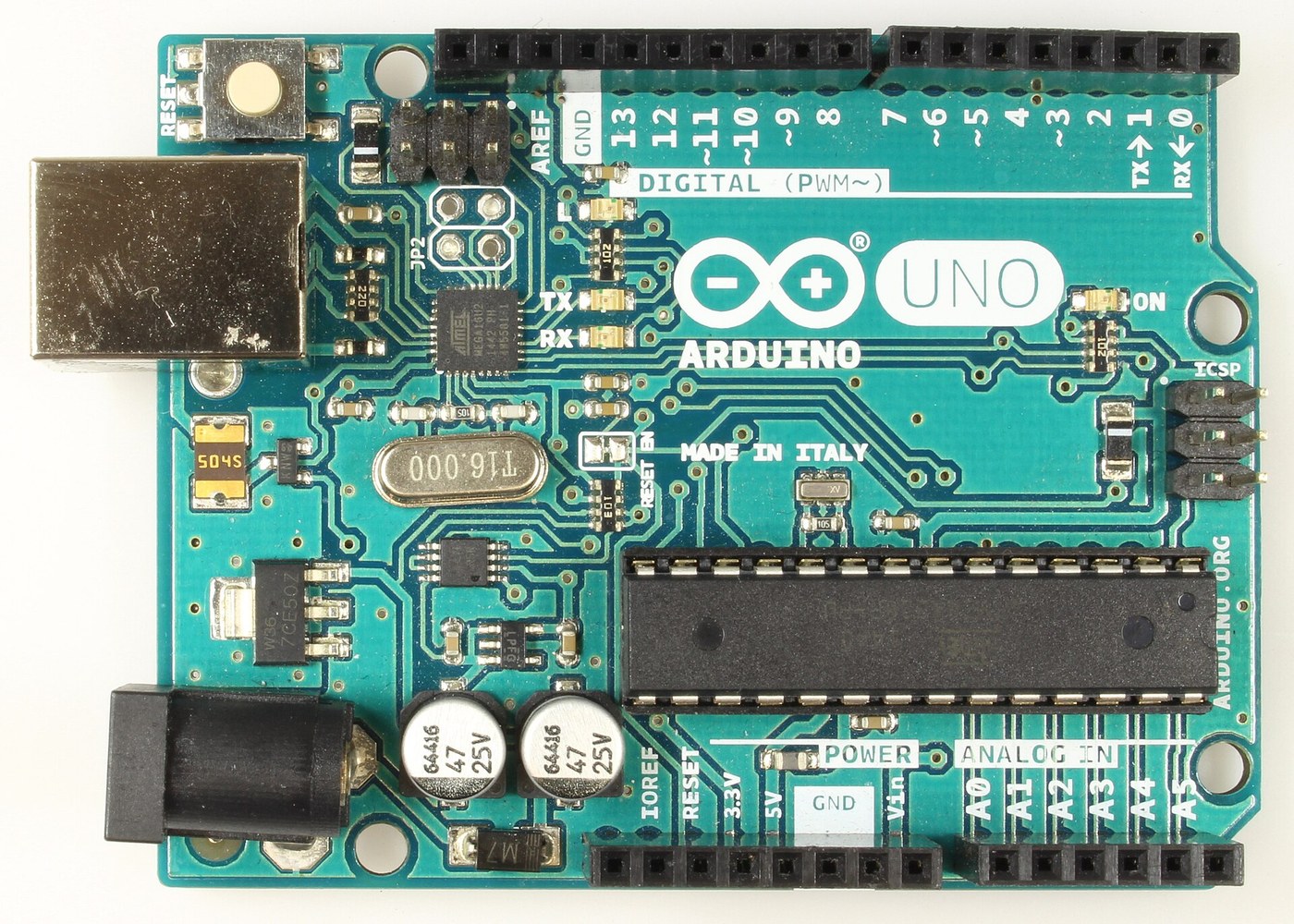


Arduino Uno R3: Assembled from Arduino's Open UNO-TH Rev3e Design Files and Flashed over ICSP
The Arduino Uno R3 is open hardware: Arduino publishes its schematic and board layout. This blueprint builds one from those files, part by part, then loads the firmware into its two processors.
Result: an Arduino Uno R3. An ATmega328P (16 MHz, 32 kB flash, 2 kB SRAM, 1 kB EEPROM) runs your programs; an ATmega16U2 turns USB into its serial link. It runs from USB (5.5 V at most) or 6-20 V at the DC jack.
Source: Arduino UNO-TH_Rev3e design files and the A000066 schematic and datasheet (Arduino, CC BY-SA). Unknown: how every bought part is made; no public source in hand says. The soldering method is ours. Picture: Wikimedia Commons.
Hejuru
1 day
Amabwiriza
1
1
Get the bare board
Get the bare board
Have the two-layer board made to Arduino's UNO-TH_Rev3e board layout (the .brd file of the design files). Check it against the schematic before fitting anything.
Ibikoresho by'iyi ntambwe:
 Ikibaho cy'umuzunguruko cyacapwe1 UNO-TH Rev3e layout
Ibikoresho bikenewe:
 Lupu Yagura
2
2
Fit the small surface-mount parts
Fit the small surface-mount parts
Solder the chip parts to their marked places: resistor arrays RN1 (10K), RN2 and RN4 (1K), RN3 (22R); R1, R2 (1M); capacitors C1, C2, C4-C7, C10 (100n), C3, C8 (1u), C9, C11 (22p); varistors Z1, Z2; ferrite bead L1; inductor L2 (10 uH); diodes D2, D3; LEDs ON (green), L, RX, TX (yellow). Ours: flux, tweezers and hot air or a fine iron, checked under a loupe.
Ibikoresho by'iyi ntambwe:
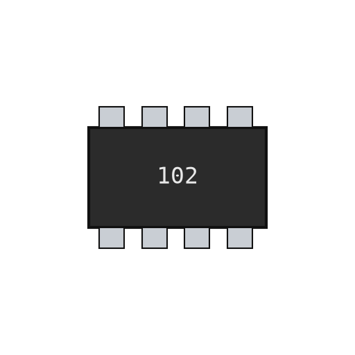 Urutonde rwa rezisitansi za shipu4 RN1-RN4
 Rezisitansi ya shipu2 1M
 Kondenseri ya seramike ya shipu11 7x100n, 2x1u, 2x22p
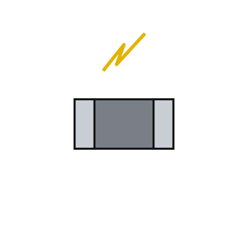 Varisitori ya shipu2 Z1, Z2
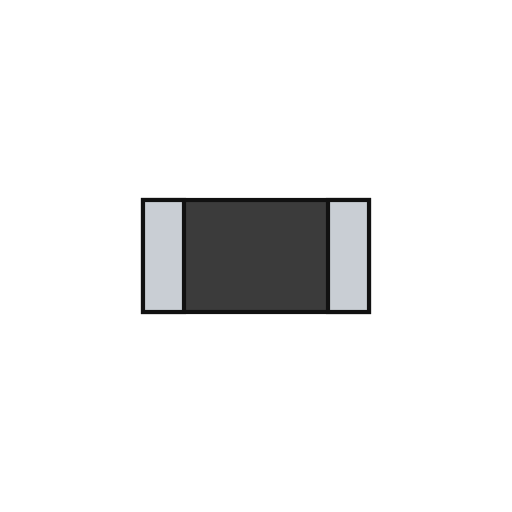 Isaro rya feriti1 L1
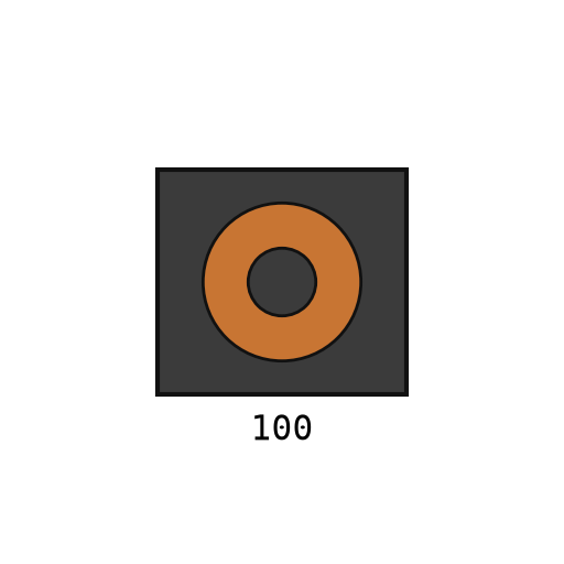 Indugitanse ishyirwa hejuru1 L2
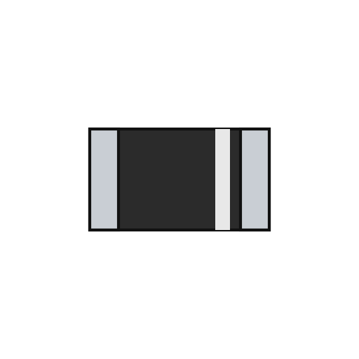 Diyode ishyirwa hejuru2 D2, D3
 LED ya shipu4 1 green, 3 yellow
 Urusinga rw'isudire1 a little
Ibikoresho bikenewe:
 Umuti wo gusudira
 Utwuma two gufata dufite impera zityaye
 Isitasiyo yo gusana n'umwuka ushyushye
 Icyuma cyo gusudiraLupu Yagura
3
3
Fit the power and chip parts
Fit the power and chip parts
Solder the ATmega16U2 (U3), the 16 MHz resonator Y2 and crystal Y1, the 5 V regulator NCP1117 (U1) and 3.3 V regulator LP2985 (U2), the LMV358 op-amp (U5), the FDN340P transistor (T1), the M7 diode (D1), the 500 mA resettable fuse (F1) and the 47 uF capacitors PC1, PC2 with their polarity as marked.
Ibikoresho by'iyi ntambwe:
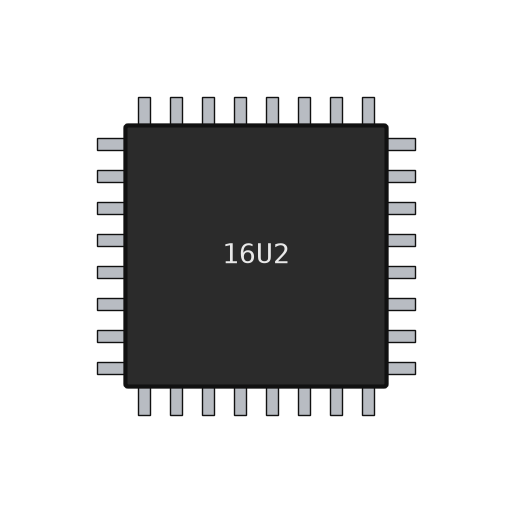 Mikorokontorolewa ATmega16U21 U3
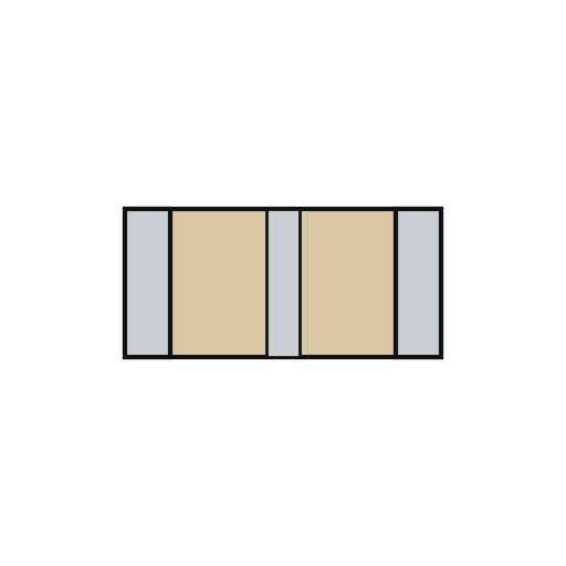 Rezonateri ya seramike ya piyezo1 Y2
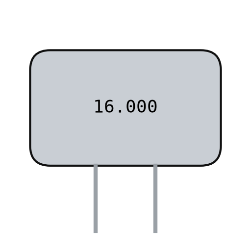 Kirisitali ya kwartsi1 Y1
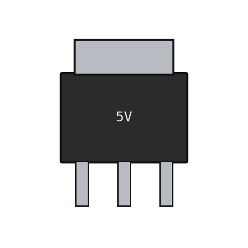 Igenzura rya voltaje ry’umurongo2 U1 5 V, U2 3.3 V
 Sirikwi ya amplifikateri y'imikorere1 U5 LMV358
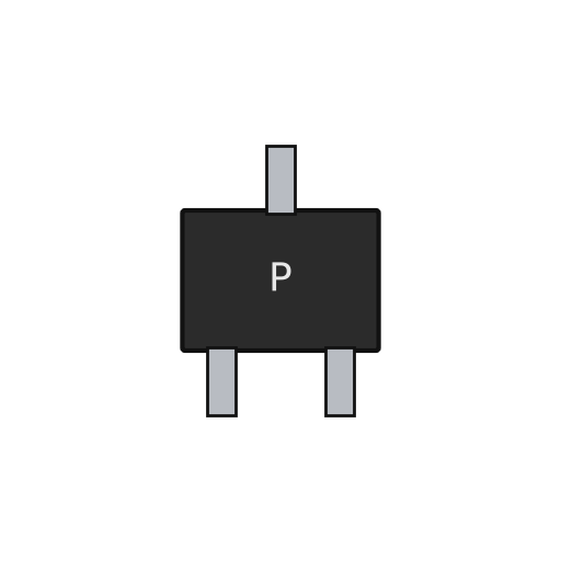 MOSFET y’umuyoboro P1 T1Diyode ishyirwa hejuru1 D1 M7
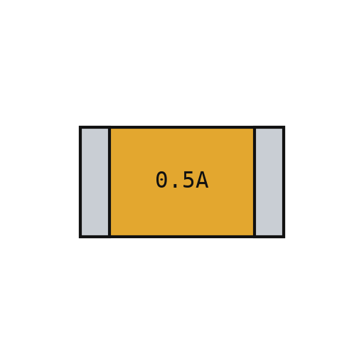 Fuzibule yisubiza1 F1
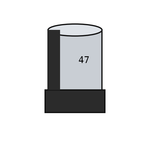 Kondenseri ya shipu ifite impande2 PC1, PC2Urusinga rw'isudire1 a little
Ibikoresho bikenewe:
Umuti wo gusudiraUtwuma two gufata dufite impera zityayeIsitasiyo yo gusana n'umwuka ushyushyeIcyuma cyo gusudiraLupu Yagura4
4
Fit the through-hole parts
Fit the through-hole parts
Solder the USB-B socket (X2), the DC jack (X1), the reset switch, the female headers (one 10-way, two 8-way, one 6-way) and the two 2x3 ICSP headers. Seat the ATmega328P in its place (ZU4).
Ibikoresho by'iyi ntambwe:
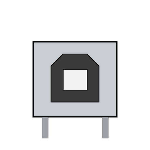 Isoketi ya USB-B1 X2
 Umwenge w'amashanyarazi uzengurutse1 X1
 Buto ikandwa1 RESET
 Umurongo w'inshinge6 10x1, 2x 8x1, 6x1 female; 2x 3x2 ICSP
 Mikorokontorolewa ATmega328P1 ZU4Urusinga rw'isudire1 as needed
Ibikoresho bikenewe:
Icyuma cyo gusudira5
5
Flash and check
Flash and check
Check with a meter that 5 V and GND are not shorted. Through the ICSP headers, load the USB-to-serial firmware into the ATmega16U2 and the bootloader into the ATmega328P. Plug in USB: the green ON LED lights, and the blink test in the next step flashes the L LED. Ours: an AVR ISP programmer and a multimeter.
Ibikoresho by'iyi ntambwe:
 Porogaramu-shingiro ya Arduino Uno1 download
Ibikoresho bikenewe:
 Igipimo cy'amashanyarazi kinyuranye
 Igikoresho cyandika porogaramu AVR ISP
 Umugozi wa USB-B
6
6
The blink test
The blink test
blink_test.ino: the same check as Arduino's Blink example. Upload it over USB from the Arduino IDE with the board set to Arduino Uno; the L LED on pin 13 turns on for one second and off for one second, over and over. If it does, both processors, the USB link and the bootloader work.
blink_test.inocpp
Ibikoresho bikenewe:
Umugozi wa USB-BIbikoresho
24- 1 UNO-TH Rev3e layoutUmwanya
- 4 RN1-RN4Umwanya
- Umwanya
- 11 7x100n, 2x1u, 2x22pUmwanya
- 2 Z1, Z2Umwanya
- 1 L1Umwanya
- Umwanya
- 1 D1 M7Umwanya
- 4 1 green, 3 yellowUmwanya
- 1 as neededUmwanya
- Umwanya
- Umwanya
- Umwanya
- 2 U1 5 V, U2 3.3 VUmwanya
- 1 U5 LMV358Umwanya
- Umwanya
- Umwanya
- 2 PC1, PC2Umwanya
- 1 X2Umwanya
- Umwanya
- Umwanya
- Umwanya
- Umwanya
- 1 downloadUmwanya
Ibikoresho bikenewe
8- Umwanya
- Umwanya
- 2 vendors sell this, none ship to you yetUmwanya
- 1 vendor sell this, none ship to you yetUmwanya
Iki gishushanyo gikora
Blueprint zijyanye
Izi blueprint zisangira ubumenyi — uburyo, ibikoresho cyangwa amahame
CC0 Umurenge rusange
Iyi blueprint yasohowe munsi ya CC0. Ushobora gukoporora, guhindura, gukwirakwiza no gukoresha nta kwemererwa.
Shyigikira Umuremyi ugura ibicuruzwa binyuze muri Blueprint ye Komisiyo y'Umuremyi byashyizweho n'Abacuruzi, cyangwa kora verisiyo nshya y'iyi Blueprint ukayinjiza nk'isano muri Blueprint yawe kugira ngo musangire inyungu.