Ubufatanye
UBUHANZI
UBWIZA N'UBUZIMA
UBUKORIKORI
UMUCO N'AMATEKA
IMYIDAGADURO
IBIDUKIKIJE
IBIRIBWA N'IBINYOBWA
UBWUBATSI BUSUBIRA INYUMA
UBUMENYI
SIPORO
IKORANABUHANGA
IBYAMBARWA
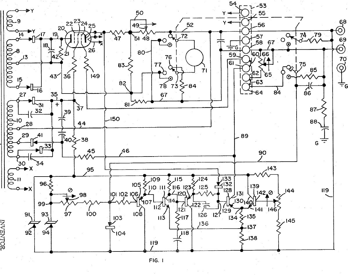


Bench Power Supply: Regulated, with Adjustable Current Limit and a Pentode Pass Tube (Gately, Forbro, US 3,243,690, 1966)
An adjustable bench supply that holds its output voltage steady and lets you set the most current it will deliver, so a circuit under test cannot be damaged. A pentode tube in series with the output is the regulator; a bridge with Zener references and a five-transistor amplifier keeps the output equal to the setting of one knob. A meter switch reads volts, amps, and the current limit, which can be set without disturbing the voltage.
Result: a regulated DC bench supply with adjustable current limiting.
Source: J. R. Gately (Forbro Design), US 3,243,690 (1966). Unknown: all component values and the output rating. Picture: the patent drawing.
Hejuru
Unknown
Amabwiriza
1
1
Wire the mains side
Wire the mains side
In a case, wire the power cord through a switch and a fuse to the primary of a transformer with four secondaries, and put a neon lamp across the primary to show the supply is on. One secondary (6.3 V) goes to two terminals for outside use, one heats the pentode, one is the main supply and one the bias supply. Ours: the case. Not given: the other winding voltages.
Ibikoresho by'iyi ntambwe:
 Agasanduku ka alumini1 case
 Umugozi w'amashanyarazi woroshye ufite purize1 igice
 Buto y'agati1 igice
 Fuzibule1 igice
 Transiforumateri Imanura Voltage1 four secondaries
 Itara ry'ikimenyetso rya neyoni1 igice
 Inkingi y'ihuza2 6.3 V terminals
Ibikoresho bikenewe:
 Igikoresho cyo gutobora gikoreshwa n'intoki
 Ikusanyirizo ry'ibitorezi
2
2
Build the rectifiers
Build the rectifiers
Rectify the centre-tapped main winding with two rectifiers and smooth it with a capacitor. From the bias winding make two more supplies: one through two rectifiers with by-pass capacitors to a smoothing capacitor, for the pentode's screen and the reference circuit; the other through one rectifier and a capacitor, for the pentode's grid bias. Not given: the values.
Ibikoresho by'iyi ntambwe:
 Diyodi5 rectifiers
 Kondenseri ya elegitorolitike3 smoothing
 Agafuka k'ibibiko by'amashanyarazi1 by-pass
 Urusinga rw'isudire1 as needed
Ibikoresho bikenewe:
 Icyuma cyo gusudira
3
3
Fit the pass tube and reference
Fit the pass tube and reference
Put the pentode in series with the positive output: plate to the main supply, cathode through two current-sensing resistors (one fixed, one adjustable) to the + output terminal; suppressor tied to the cathode, screen fed through a resistor. Build the reference: a Zener fed through a resistor feeds a second Zener at constant current, giving a fixed voltage. Against it set two resistors and the voltage-control variable resistor: the output voltage is proportional to that resistor's setting. Not given: the tube type and values.
Ibikoresho by'iyi ntambwe:
 Itara rya pentode1 series pass tube
 Diyode ya Zener2 ibice
 Ubukomezi bw'amashanyarazi1 ikirundo
 Rewositati2 voltage control, current-limit rangeInkingi y'ihuza2 output + and -Urusinga rw'isudire1 as needed
Ibikoresho bikenewe:
Icyuma cyo gusudira4
4
Build the error amplifier and current limit
Build the error amplifier and current limit
Build a five-transistor amplifier that drives the pentode's grid to keep the bridge balanced: a PNP emitter follower, an NPN stage, a PNP emitter follower with a resistor-capacitor roll-off against oscillation, a PNP driver whose base resistor has a capacitor across it for quick response, and an NPN clamp whose base is set by a potentiometer. Feed the voltage across the current-sensing resistors to the driver's base through a diode: above the limit it takes over and turns the pentode down. Choose the fixed sensing resistor to limit at about 125 % of rated current, trim with the potentiometer, and use the adjustable one to set lower limits. Not given: the transistor types and values.
Ibikoresho by'iyi ntambwe:
 Tranzisitori ya PNP3 ibice
 Tarangisitori ya NPN2 ibiceDiyodi1 igice
 Potensiyometero1 igiceAgafuka k'ibibiko by'amashanyarazi1 roll-off, speed-upUbukomezi bw'amashanyarazi1 ikirundoUrusinga rw'isudire1 as needed
Ibikoresho bikenewe:
Icyuma cyo gusudira5
5
Fit the meter and use it
Fit the meter and use it
Fit a meter with a four-pole, three-position switch. Position 1 reads output volts through a multiplier resistor; position 2 reads current across a shunt in the negative line; position 3 (spring-return) puts a load resistor across the output and swaps a fixed resistor for the voltage control, so you can turn the limit control until the current limits at the value you want, without touching the voltage setting. Release the switch and use the supply.
Ibikoresho by'iyi ntambwe:
 Igipimo cyo ku rubaho gifite bobine igenda1 igice
 Swichi izunguruka1 4-pole, 3-positionUbukomezi bw'amashanyarazi1 multiplier, shunt, load resistors
 Ibikoresho bitazwi1 terminal strip
Ibikoresho bikenewe:
Icyuma cyo gusudiraIkusanyirizo ry'ibitoreziIbikoresho
21- 1 caseUmwanya
- Umwanya
- Umwanya
- 1 igiceUmwanya
- 1 four secondariesUmwanya
- Umwanya
- Umwanya
- 1 igiceUmwanya
- 3 smoothingUmwanya
- 1 roll-off, speed-upUmwanya
- 3 as neededUmwanya
- 1 series pass tubeUmwanya
- 2 ibiceUmwanya
- 1 multiplier, shunt, load resistorsUmwanya
- 2 voltage control, current-limit rangeUmwanya
- 3 ibiceUmwanya
- 2 ibiceUmwanya
- Umwanya
- Umwanya
- 1 4-pole, 3-positionUmwanya
- 1 terminal stripUmwanya
Iki gishushanyo gikora

CC0 Umurenge rusange
Iyi blueprint yasohowe munsi ya CC0. Ushobora gukoporora, guhindura, gukwirakwiza no gukoresha nta kwemererwa.
Shyigikira Umuremyi ugura ibicuruzwa binyuze muri Blueprint ye Komisiyo y'Umuremyi byashyizweho n'Abacuruzi, cyangwa kora verisiyo nshya y'iyi Blueprint ukayinjiza nk'isano muri Blueprint yawe kugira ngo musangire inyungu.