Ubufatanye
UBUHANZI
UBWIZA N'UBUZIMA
UBUKORIKORI
UMUCO N'AMATEKA
IMYIDAGADURO
IBIDUKIKIJE
IBIRIBWA N'IBINYOBWA
UBWUBATSI BUSUBIRA INYUMA
UBUMENYI
SIPORO
IKORANABUHANGA
IBYAMBARWA
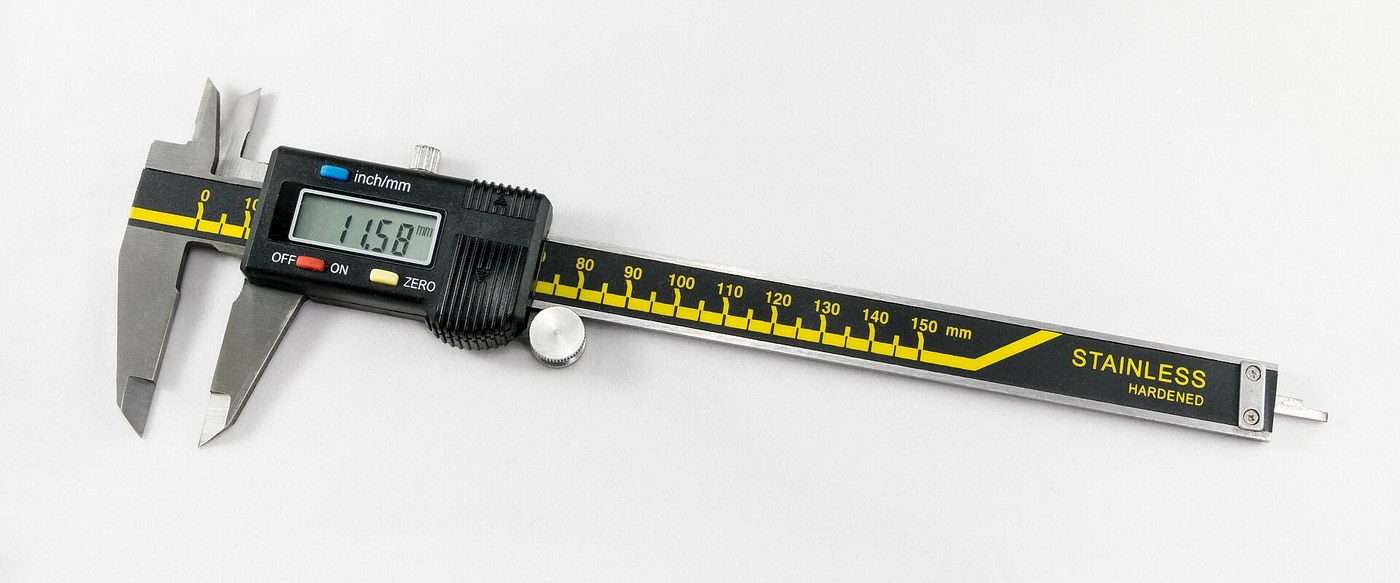


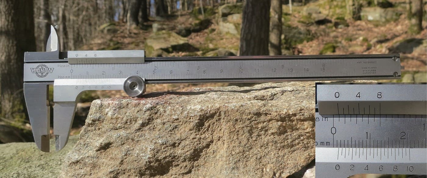
Digital Caliper: Capacitive Scale and Slider with Two-Chip Electronics (Baxter and Buehler, Starrett, 1986)
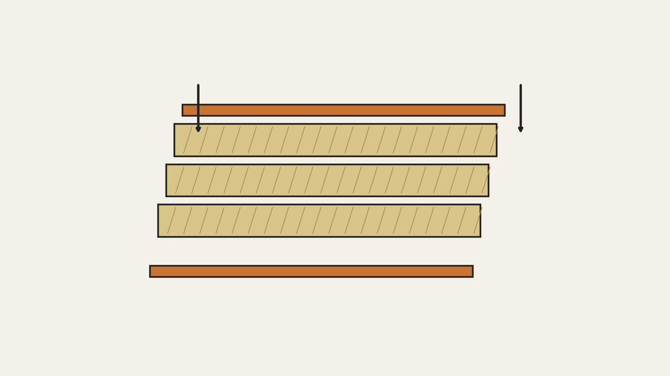
A six-inch caliper that reads out on a display. Under the slide, a strip of etched copper bars runs along the beam. Electrodes on the slider pass a signal through the bars by capacitance, and the slider's electronics count the bars crossed and work out the position in between.
Result: a digital caliper reading in inches or millimetres, repeatable to a ten-thousandth of an inch, with floating zero, peak hold and high/low limits. It runs on two 1.5 V cells at 10-50 microamps.
Source: L. K. Baxter and R. J. Buehler (L. S. Starrett Co.), US Patent 4,586,260 (1986). Unknown: the metal of the beam, slide and rod, their dimensions, the processor's program, and how the chips and display are made. Ours: the etchant, photoresist and glue. Picture: Wikimedia Commons.
Hejuru
2 days
Amabwiriza
1
1
Etch the scale
Etch the scale
Etch the scale pattern onto a strip of copper-clad epoxy fibreglass with photoresist and etchant. Each copper bar is 0.40 inch long, with a wider centre 0.12 inch long and two ends 0.14 inch long. Space the bars on 0.05 inch centres: the centres sit 0.004 inch apart, the ends 0.025 inch apart. Run the pattern the full length of the scale. Ours: dry film resist and ferric chloride.
Ibikoresho by'iyi ntambwe:
 Ikibaho cy'umuzunguruko kirimo ubusa (gifite umuringa)1 strip, length of the beam
Ibikoresho bikenewe:
 Firimi yumye ihagarika urumuri
 Umuti wa kloride y'icyuma
 Uturindantoki Turwanya Ibinyabutabire
2
2
Fix the scale into the beam
Fix the scale into the beam
The beam is a metal bar with the fixed outside and inside jaws at one end, a wide shallow channel in its face and a second channel along its back. Fix the scale permanently into the face channel, copper up. The patent allows etching before or after this step. Not given: the metal, the dimensions and how the scale is fixed. Ours: epoxy.
Ibikoresho by'iyi ntambwe:
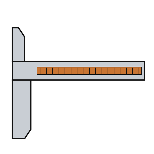 Inkoni ya kalipa1 with integral jaws
 Epoksi y'Ibice Bibiri1 a little
Ibikoresho bikenewe:
 Ingano zitazwi
3
3
Fit the parts to the circuit
Fit the parts to the circuit
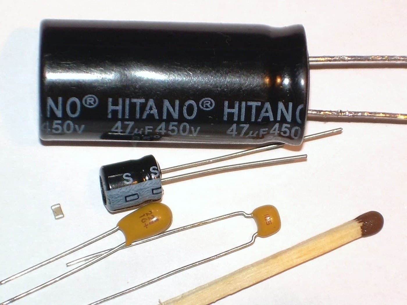
The circuit is one folded piece: a double-sided slider board joined by a flexible hinge to a circuit board. Its bottom face has two pickup electrodes, 0.750 x 0.110 inch and 0.0625 inch apart. On each side of them is an interdigitated transmitter array: fingers 0.115 inch long on 0.025 inch spacing, opening to 0.0375 inch at the centre. On the circuit board, solder or wire-bond the two chips: an NEC uPD7503 3 V processor (768 bits RAM, 2 kB ROM) and a CMOS gate array. Then fit the LCD, the 100 kHz crystal, the integrating capacitor and the MODE and SET buttons. Not given: the processor's program. Ours: a capacitor from a kit.
Ibikoresho by'iyi ntambwe:
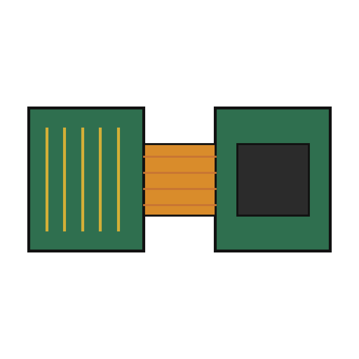 Ikibaho cy'umuzunguruko gikomeye kandi kigoroka1 slider board + circuit board
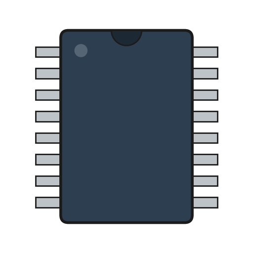 IC2 uPD7503 CPU, CMOS gate array
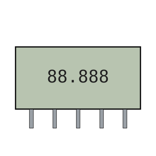 Icyerekana LCD cy'ibice1 5 digits
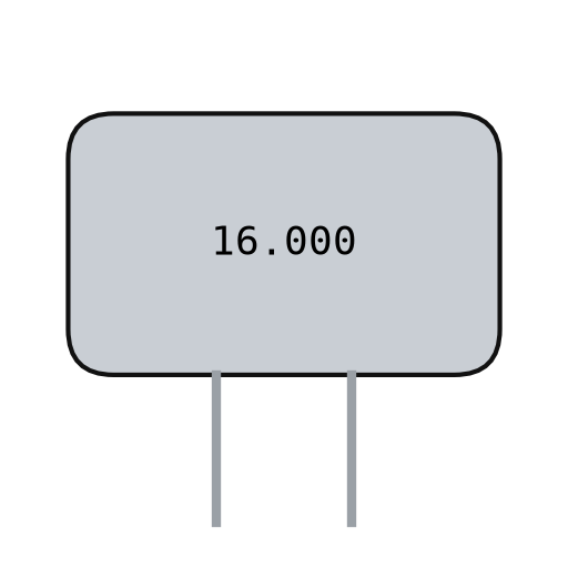 Kirisitali ya kwartsi1 100 kHz
 Agafuka k'ibibiko by'amashanyarazi1 one integrating capacitor
 Buto ikandwa2 MODE, SET
 Urusinga rw'isudire1 a little
Ibikoresho bikenewe:
 Icyuma cyo gusudira
4
4
Build the slide
Build the slide
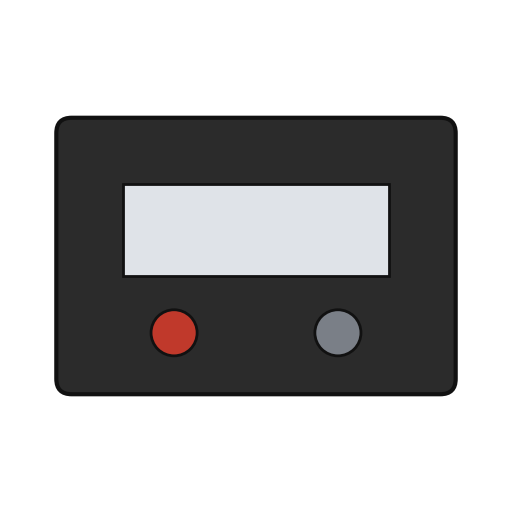
The slide frame wraps the back and edges of the beam and carries the movable jaws. Fix it to the depth rod, which runs in the back channel of the beam; the rod's free end is the depth gauge. Put the moulded plastic housing between the frame ends. Fasten two metal wear strips under the slider board, one on each side of the scale. They ride on the beam and connect the board's copper to it. Not given: the metal and sizes.
Ibikoresho by'iyi ntambwe:
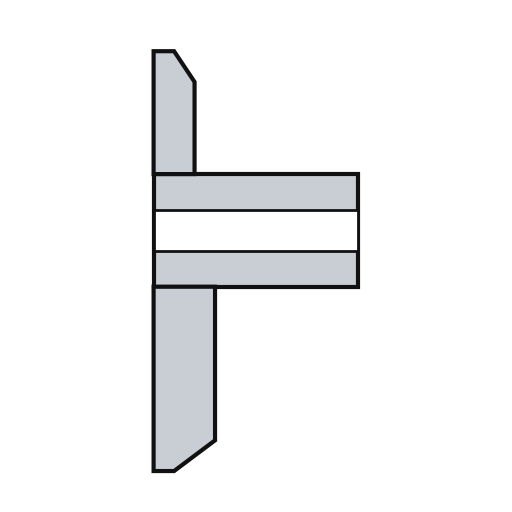 Ikadiri y'agasunika1 with jaws
 Icyuma kitazwi1 depth rod and two wear strips
 Igikonoshwa cy'agasunika1 igice
Ibikoresho bikenewe:
Ingano zitazwi Agatsiko ka tuneviza nyayo
5
5
Assemble and check
Assemble and check
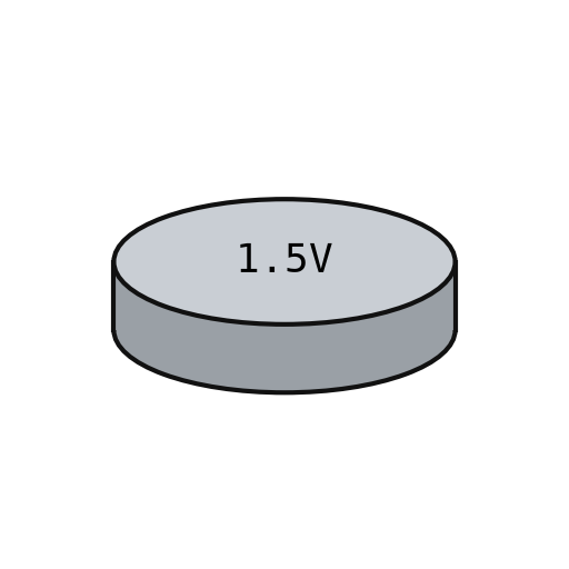
Fold the circuit into the housing recess, slider board facing the scale, and screw it to the frame. The electrodes must lie parallel to the scale bars at every point of travel. Put the two 1.5 V cells (the patent says 'zinc oxide') in the battery pockets of the circuit. The display shows five digits, a ten-thousandths bar graph, a minus sign and 'mm', plus PEAK, LOW, HIGH and LIMIT. Ours: check the reading against a vernier caliper.
Ibikoresho by'iyi ntambwe:
 Ibitorezo by'imashini2 ibice
 Bateri y'akabuto ya volti 1.52 ibice
Ibikoresho bikenewe:
Agatsiko ka tuneviza nyayo Kalipe ya Vernier
Ibikoresho
15- 1 strip, length of the beamUmwanya
- 1 with integral jawsUmwanya
- 1 a littleUmwanya
- 1 slider board + circuit boardUmwanya
- 2 uPD7503 CPU, CMOS gate arrayUmwanya
- 1 5 digitsUmwanya
- 1 100 kHzUmwanya
- 1 one integrating capacitorUmwanya
- Umwanya
- 1 a littleUmwanya
- 1 with jawsUmwanya
- 1 depth rod and two wear stripsUmwanya
- 1 igiceUmwanya
- 2 ibiceUmwanya
- Umwanya
Ibikoresho bikenewe
7- Umwanya
- Umwanya
- 2 vendors sell this, none ship to you yetUmwanya
- Umwanya
- Umwanya
Ibikoresho by'Ibishushanyo Bifitanye Isano

Iki gishushanyo gikora

Blueprint zijyanye
Izi blueprint zisangira ubumenyi — uburyo, ibikoresho cyangwa amahame
CC0 Umurenge rusange
Iyi blueprint yasohowe munsi ya CC0. Ushobora gukoporora, guhindura, gukwirakwiza no gukoresha nta kwemererwa.
Shyigikira Umuremyi ugura ibicuruzwa binyuze muri Blueprint ye Komisiyo y'Umuremyi byashyizweho n'Abacuruzi, cyangwa kora verisiyo nshya y'iyi Blueprint ukayinjiza nk'isano muri Blueprint yawe kugira ngo musangire inyungu.