Building a Simple DC Electric Motor — Electromagnetic Rotation
Consignes
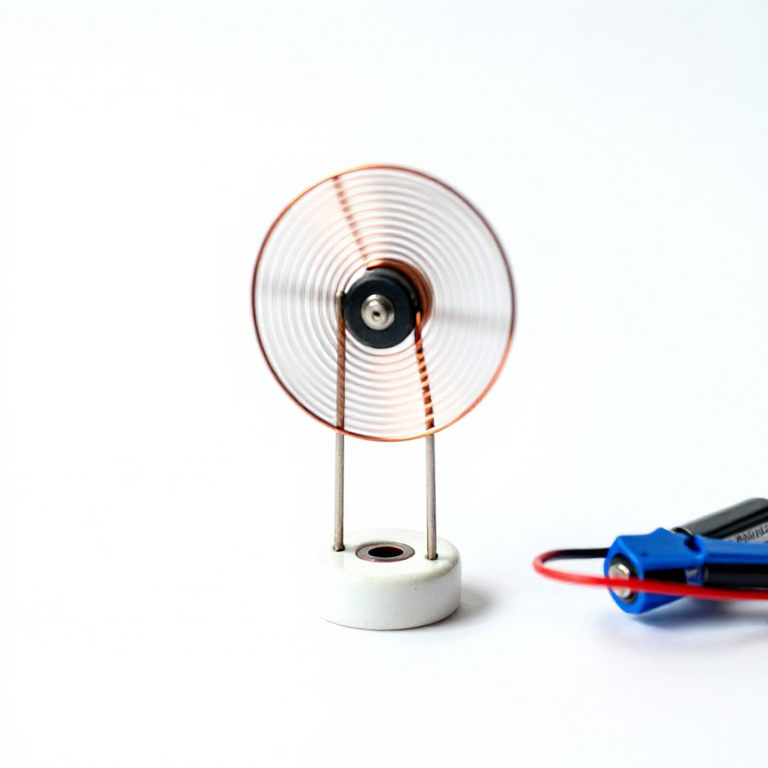
Wind the Armature Coil
Wind the Armature Coil
Wrap the enameled copper wire around a cylindrical form (a battery or marker pen works well) 5-10 times to create a flat, circular coil approximately 3-4cm in diameter. Leave 3-4cm of straight wire extending from each side of the coil as axle shafts. These shafts must be directly opposite each other and aligned along the same axis so the coil can spin freely. Wrap a short length of wire around the coil bundle at two points to keep the loops together. The coil should be balanced — if one side is heavier, it will not spin smoothly.
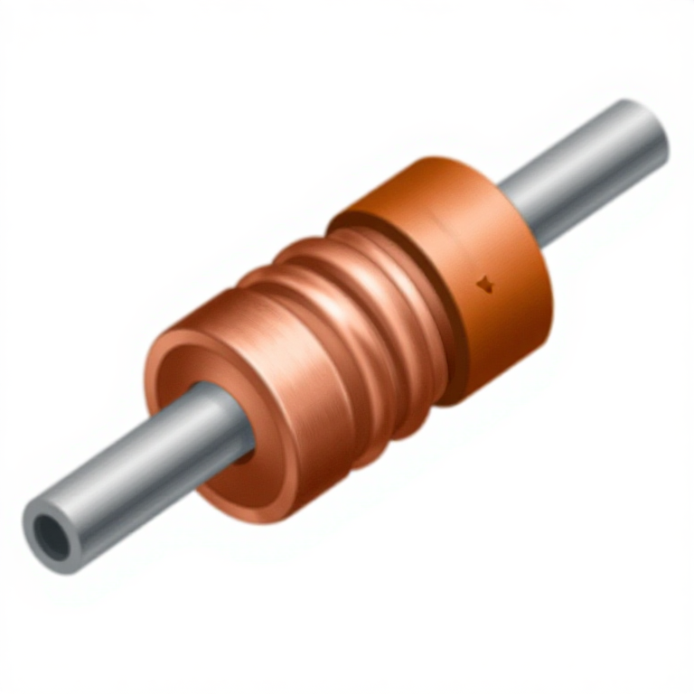
Create the Half-Commutator
Create the Half-Commutator
This is the critical step. Strip the enamel insulation from one axle shaft completely (all around its circumference) using fine sandpaper. On the other axle shaft, strip the enamel from only one half of the circumference — leave the other half insulated. This half-stripped shaft acts as a simple commutator: when the bare side contacts the support, current flows through the coil and generates a magnetic field. When the coil rotates 180 degrees and the insulated side contacts the support, current is interrupted and the coil coasts on momentum. This on-off cycling with each rotation ensures the magnetic force always pushes in the same rotational direction.
Build the Support Cradle
Build the Support Cradle
Unfold two large steel paper clips into an L-shape or hook shape that can support the coil axle shafts while allowing free rotation. The vertical section acts as a post, and a small loop or cradle at the top holds the axle shaft. Attach the paper clip supports to the battery terminals using rubber bands — one clip to the positive terminal, one to the negative terminal. Position the clips so their top cradles are at the same height and aligned so the coil hangs horizontally between them. The paper clips serve double duty: they support the coil mechanically and conduct electrical current from the battery to the coil axle shafts.
Matériaux pour cette étape :
 Enameled Copper Wire 22 AWG1m m
 Neodymium1, approximately 20mm diameter mm
 18650 Battery Holder 4-Cell1 pièce
Position the Magnet
Position the Magnet
Place the permanent magnet on top of the battery, directly beneath the coil (or tape it to a support at coil level). The magnet's field should be perpendicular to the coil's axis of rotation. When current flows through the coil, the coil generates its own magnetic field. The interaction between the coil's field and the permanent magnet's field creates a torque (rotational force) on the coil. The closer the magnet is to the coil without touching, the stronger the force and faster the rotation. A neodymium magnet produces a much stronger field than a ceramic magnet and results in faster, more reliable rotation.
Start the Motor and Observe
Start the Motor and Observe
Give the coil a gentle push to start it spinning. If the half-commutator is correctly made and the coil is balanced, it will accelerate and continue spinning on its own. The coil experiences a magnetic force during the half-rotation when current flows (bare enamel contacting the support), then coasts on angular momentum during the half-rotation when current is interrupted (insulated side contacting the support). If the motor does not sustain rotation, check: is the coil balanced and spinning freely without friction? Is the enamel fully stripped from the correct surfaces? Is the magnet close enough? Try reversing the magnet's polarity or the battery connection — if the initial push direction fights the magnetic force direction, the motor cannot sustain. This simple motor demonstrates the operating principle behind every electric motor in existence, from tiny phone vibration motors to industrial drives.
Matériaux
5- 1m pièceEspace réservé
- 1 pièceEspace réservé
- 2 piècesEspace réservé
- 2 piècesEspace réservé
Outils requis
2- Espace réservé
- Espace réservé
You can swap these in
Can't get one of the materials? Swap it for an equivalent — these work just as well.
- Instead of Enameled Copper Wire 22 AWG, try:
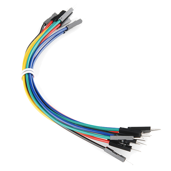 Jumper Wires Premium M/M 20 AWG - 15.5 cm (Pack of 10)
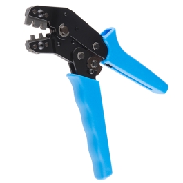 Crimping Pliers - 28-20 AWG
 - Instead of Pliers Set, try:
 Tongue & Groove Pliers
 Support Removal Pliers (Flush Cut)
 Flat-Nose Pliers
 Grozing Pliers
 Locking Pliers
 Needle-Nose Pliers
 - Instead of Notebook and Pencil, try:
 Carpenter's Pencil Set (24-Pack)
 Graphite Pencil Set
 Pencil (Carpenter's Marking)
 - Instead of Rubber Bands, try:
 Canning Lids & Bands
Recommended for this build
Products makers often use with builds like this one.

Related blueprints
Other builds that share materials, tools, or techniques with this one.
CC0 Domaine public
Ce blueprint est publié sous CC0. Vous êtes libre de copier, modifier, distribuer et utiliser ce travail pour tout usage, sans demander la permission.
Soutenez le Maker en achetant des produits via son Blueprint où il perçoit une Commission Maker définie par les Vendeurs, ou créez une nouvelle itération de ce Blueprint et incluez-le comme connexion dans votre propre Blueprint pour partager les revenus.