UBUHANZI
UBWIZA N'UBUZIMA
UBUKORIKORI
UMUCO N'AMATEKA
IMYIDAGADURO
IBIDUKIKIJE
IBIRIBWA N'IBINYOBWA
UBWUBATSI BUSUBIRA INYUMA
UBUMENYI
SIPORO
IKORANABUHANGA
IBYAMBARWA
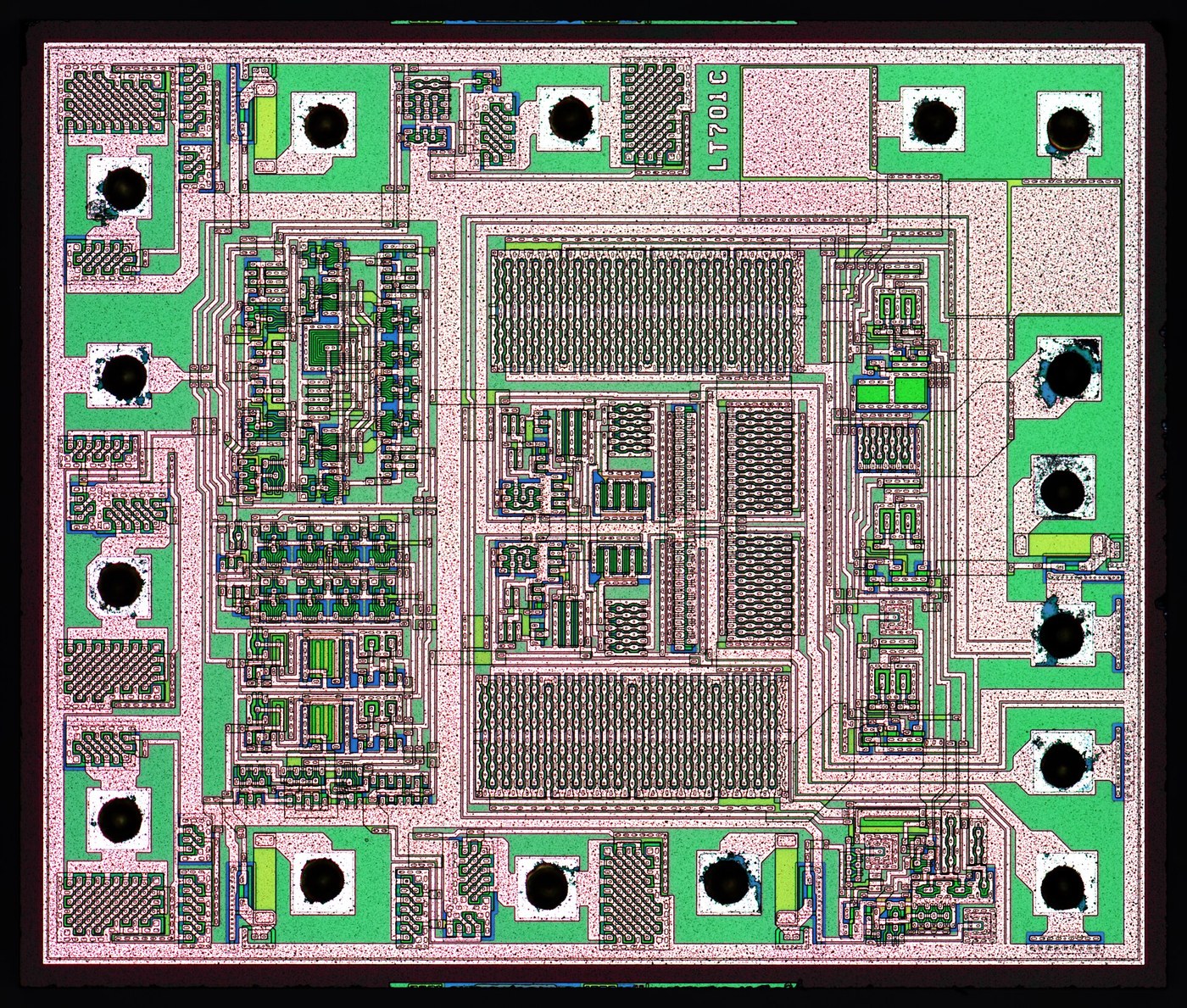


The Phase-Locked Loop
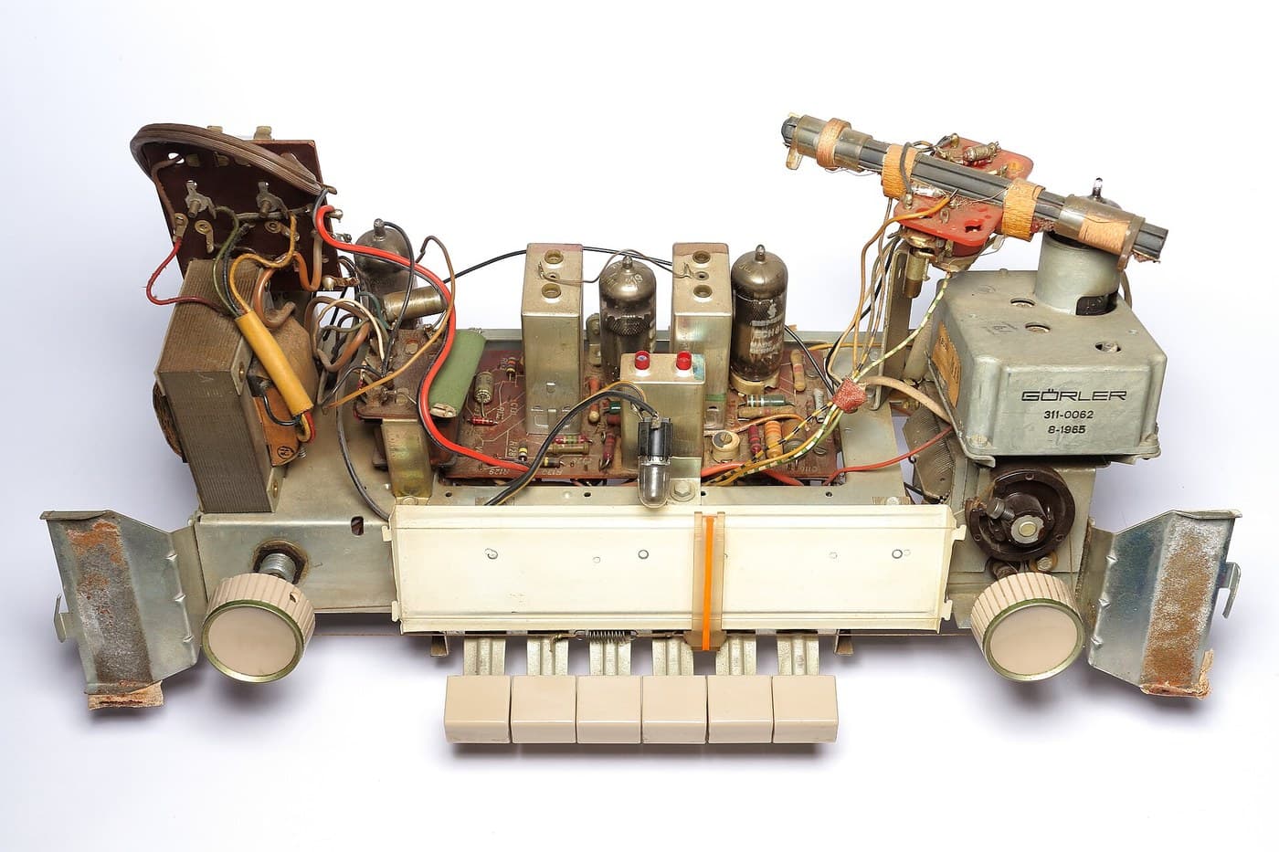
Every loop so far feeds back an amplitude - a voltage, an angle, a speed - and settles when the correction balances the error, which means a little error always remains. Henri de Bellescize's synchronous receiver of 1932 feeds back something else: the PHASE difference between an incoming signal and a local oscillator.
That one change buys a property no amplitude loop can offer. Frequency is the rate of change of phase, so an oscillator is already an integrator. Hold the phase error at any constant value and the two frequencies must be EXACTLY equal - not close, equal to the last decimal place - for as long as the lock holds. The remaining error is pushed entirely into the phase, which sits wherever it must to keep the oscillator pulled to the right frequency.
Three blocks do it. A phase detector, which is a multiplier; a loop filter, which decides the dynamics; and a voltage-controlled oscillator, which is the plant. The filter's time constant sets a trade you cannot avoid: a narrow loop rejects noise and rides through a dropout but takes a long time to acquire, and a wide loop locks instantly and passes the noise straight onto the recovered clock.
It is worth seeing this next to the regenerative receiver, because they are the same circuit pushed in opposite directions. Regeneration uses positive feedback and is set as close to oscillating as the operator dares. A phase-locked loop lets its oscillator run freely and uses negative feedback to drag it into step with something outside. One asks a human to hold a circuit on the edge of instability; the other never goes near it - which is why a locked receiver can be sealed in a box and forgotten.
Hejuru
3 hours
Amabwiriza
1
1
A VCO and a phase detector
A VCO and a phase detector
Wire a 555 as an astable near 5 kHz and bring its control pin out - that pin is a voltage-controlled oscillator, and a few hundred millivolts on it swings the frequency by a good fraction.
Feed the 555 output and a signal from the generator into an XOR gate. Its average output voltage is the phase difference, which you can see on a meter as you sweep the generator past the 555's free-running frequency.
Ibikoresho by'iyi ntambwe:
 Umuzunguzo w'igihe NE5551 agapaki
 Ibyuma bito bya logique binyuranye1 ibikoresho
 Ikusanyirizo ry'Ibirwanya Amashanyarazi bya 1/4 W1 ibikoresho
 Agafuka k'ibibiko bya seramike1 ibikoresho
Ibikoresho bikenewe:
 Ikibaho cy'Ibizamini
 Igikorera ibimenyetso cya DDS
 Osilosikopu ya Digitale
 Igipimo cya Digitale cy'Urwego rw'Ubushakashatsi
2
2
Close the loop and find the edges of lock
Close the loop and find the edges of lock
Filter the XOR output with a 10k and 1 uF and take it to the 555's control pin. Sweep the generator slowly: at some point the 555 snaps into step and stays there while you keep tuning.
Note the two frequencies where it grabs and the two where it lets go. The capture range is narrower than the hold range, and swapping the capacitor for 100 nF changes both - that is the loop filter setting the dynamics.
Ibikoresho by'iyi ntambwe:
 Ibikoresho bya kapasitori za elegitoroliti1 ibikoreshoIkusanyirizo ry'Ibirwanya Amashanyarazi bya 1/4 W1 ibikoresho
Ibikoresho bikenewe:
Ikibaho cy'IbizaminiIgikorera ibimenyetso cya DDSOsilosikopu ya DigitaleIgipimo cya Digitale cy'Urwego rw'Ubushakashatsi3
3
Lock range, loop dynamics, and four receivers
Lock range, loop dynamics, and four receivers
Gupakira ikaye ya Jupyter…
Ibikoresho bikenewe:
 Mudasobwa yo ku Meza
4
4
Compendium: locking to the wrong thing
Compendium: locking to the wrong thing
A phase detector made from a multiplier or an XOR cannot tell a signal from its harmonics, so a loop free-running near 5 kHz will happily lock to a 2.5 kHz input at twice the rate, or to 15 kHz at a third. In a laboratory that is a puzzle; in a receiver it is a wrong station. The cures are all about restricting where the oscillator is allowed to be before the loop is closed - a narrow VCO tuning range, a coarse frequency detector that steers the loop into the right region first, or a phase-frequency detector, which uses two flip-flops to report which signal is AHEAD rather than merely how far apart they are, and so cannot be fooled by a harmonic at all.
Capture range and hold range are different numbers, and the experiment shows it. Once locked, the loop holds until the phase error runs out of room - the full loop gain. Unlocked, the detector output is a beat note the filter mostly throws away, so the loop only pulls itself in from a much narrower band. Every PLL therefore has a region where it stays locked if it already is and never finds lock on its own, which is why synthesisers carry a lock detector and a sweep circuit.
Ibikoresho
5- 1 agapakiUmwanya
- 1 ibikoreshoUmwanya
- Umwanya
- 1 ibikoreshoUmwanya
- 1 ibikoreshoUmwanya
Ibikoresho bikenewe
5- 1 vendor sell this, none ship to you yetUmwanya
- 1 vendor sell this, none ship to you yetUmwanya
- Umwanya
Blueprint zijyanye
Izi blueprint zisangira ubumenyi — uburyo, ibikoresho cyangwa amahame

CC0 Umurenge rusange
Iyi blueprint yasohowe munsi ya CC0. Ushobora gukoporora, guhindura, gukwirakwiza no gukoresha nta kwemererwa.
Shyigikira Umuremyi ugura ibicuruzwa binyuze muri Blueprint ye Komisiyo y'Umuremyi byashyizweho n'Abacuruzi, cyangwa kora verisiyo nshya y'iyi Blueprint ukayinjiza nk'isano muri Blueprint yawe kugira ngo musangire inyungu.