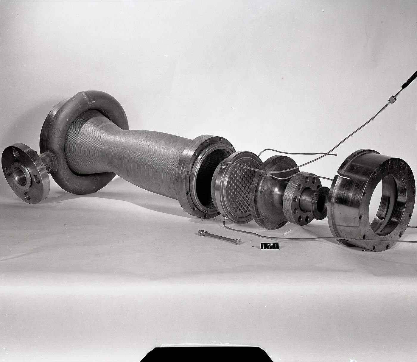


Regenerative Cooling
Amabwiriza
Prove a thin wall with flowing water cannot get hot
Prove a thin wall with flowing water cannot get hot
The counter-intuitive claim first, demonstrated with a blowtorch and a copper tube.
- Take a thin-walled copper tube and run water through it at a good rate.
- Play a propane torch directly on the outside and measure the OUTER wall temperature with an infrared thermometer.
- Measure the water temperature in and out.
- Now stop the flow, briefly, and watch the wall temperature.
With water flowing, the wall sits barely above the water temperature even under direct flame; the moment flow stops it climbs immediately toward destruction.
The reason is that heat must cross three resistances in series — gas to wall, through the wall, wall to coolant — and the wall’s own resistance is tiny if it is thin and made of copper. Wall temperature is set almost entirely by the coolant side, not by the flame. Which is why chamber liners are made of copper alloy rather than something with a high melting point: conductivity beats heat resistance.
That is worth pausing on, because it inverts the obvious approach. You do not fight a 3300°C fire by finding a material that survives 3300°C — no such material is practical. You fight it by making sure the material never experiences it.Ibikoresho by'iyi ntambwe:
 Umuyoboro w'umuringa1 igice
Ibikoresho bikenewe:
 Itara rya Propane
 Igipima Ubushyuhe cya Inifurarouje
 Kamera ifata amashusho y'ubushyuhe
 Termokupuli ifite igaragaza
 Igipima Umuvuduko
 Amadarubindi Asobanutse yo Kwirinda
 Ingabo y'Isura
 Ikizimya umuriro
 Propane
Machine cooling channels and compute the heat load
Machine cooling channels and compute the heat load
Size the passages from the heat they must remove, not by eye.
- Estimate the heat flux at the chamber wall — for a small engine, a few megawatts per square metre is a realistic starting figure, and it PEAKS at the nozzle throat.
- Multiply by wall area to get total heat load.
- Divide by the coolant’s mass flow and specific heat capacity to find its temperature rise.
- Machine axial channels in a copper liner sized to give the required coolant velocity.
The throat is where the heat flux peaks, often by a factor of two or three over the chamber, because the gas is fastest and densest there. So the channels must be narrowest at the throat, where the coolant is forced to speed up exactly where it is needed most.
Reverse-engineering note: this is why a rocket chamber is not a plain tube but a machined liner with dozens of individually-contoured channels, closed out by an electroformed or brazed outer jacket. The channel cross-section varies continuously along the length, and that variation is the cooling design.Ibikoresho by'iyi ntambwe:
 Igice cy'umuringa1 igice
 Urupapuro rw'Imirongo1 pad
Ibikoresho bikenewe:
 Imashini yo guhinguza icyuma
 Ifashi ry'imashini yo gusya inch 4
 Ikigereranyo cya Digitale cy'Amasentimetero 6
 MikorometeroIgipima Ubushyuhe cya InifuraroujeTermokupuli ifite igaragazaAmadarubindi Asobanutse yo Kwirinda
Find the boiling limit that ends the party
Find the boiling limit that ends the party
Liquid cooling has one abrupt failure mode and it is worth meeting deliberately, at small scale.
- Heat a small test section with a controlled electrical heater and flow coolant through it.
- Raise the heat input in steps, recording wall temperature at each.
- Continue past the point where small bubbles first appear at the wall.
- Stop the moment wall temperature starts climbing rapidly for no extra heat input.
Wall temperature rises gently, and then at a certain flux it jumps sharply. Below that point bubbles form at the wall and immediately collapse back into the cooler bulk liquid — nucleate boiling, which actually improves heat transfer. Above it the bubbles merge into a continuous vapour film that insulates the wall from the liquid entirely.
That is departure from nucleate boiling, and it is not a gradual degradation. The wall goes from well-cooled to uncooled in milliseconds, and a copper liner burns through immediately.
Keeping coolant pressure ABOVE its critical pressure avoids the problem entirely, because above the critical point there is no distinction between liquid and vapour and therefore no film to form. This is one reason regenerative circuits run at such high pressure — not only to reach the injector, but to stay out of the boiling regime altogether.Ibikoresho by'iyi ntambwe:
Umuyoboro w'umuringa1 igiceUrupapuro rw'Imirongo1 padIbikoresho bikenewe:
Termokupuli ifite igaragazaIgipima Ubushyuhe cya InifuraroujeIgipima Umuvuduko Iminzani ya DigitaleAmadarubindi Asobanutse yo KwirindaIngabo y'Isura
 Icyuma gishyushya cy'urupapuro
Add film cooling as the second line of defence
Add film cooling as the second line of defence
Protect the wall from inside as well as outside.
- Add a ring of small holes near the injector face, angled to direct fuel ALONG the chamber wall rather than into the core.
- Cold-flow and confirm a continuous liquid film forms on the wall.
- Measure how far downstream the film survives before breaking up.
- Compute the propellant fraction being spent on it.
A thin layer of fuel flowing along the wall keeps the hottest gas physically away from the metal, and its evaporation absorbs heat where it matters most. Typically a few percent of total fuel flow is diverted this way.
The cost is real: that fuel burns at a lower mixture ratio than optimal, so it produces less energy per kilogram, and specific impulse drops slightly. You are deliberately running the engine worse in order to keep it intact.
Some engines take this further and run the entire outer injector ring fuel-rich, accepting a measurable Isp penalty for a large margin against wall failure. The choice is not efficiency versus laziness — it is efficiency versus the engine existing at the end of the burn.Ibikoresho by'iyi ntambwe:
 Urupapuro rw'umuringa1 igice
 Ibara ry'ibiribwa (ibara ryo kugaragaza uko amazi atembera)1 icupa
Ibikoresho bikenewe:
 Icyuma Cyivumbura GihagazeIfashi ry'imashini yo gusya inch 4Ikigereranyo cya Digitale cy'Amasentimetero 6
 Terefone Ifata Amashusho Agenda BuhoroIgipima UmuvudukoIgipima Ubushyuhe cya InifuraroujeAmadarubindi Asobanutse yo Kwirinda
Close the loop, and see the heat come back as thrust
Close the loop, and see the heat come back as thrust
Now connect the coolant outlet to the injector and understand why this is called regenerative.
- Trace the full path: tank, pump, cooling channels, injector, chamber.
- Measure the coolant temperature rise across the channels from the earlier test.
- Consider where that absorbed energy goes once the warmed fuel is injected and burned.
The heat removed from the wall is not dumped overboard — it is carried into the chamber inside the fuel and released again during combustion. Almost none of it is lost. The cooling system is thermodynamically nearly free, which is why it beats every alternative.
Compare the alternatives honestly. Ablative cooling lines the chamber with material that chars and erodes away, carrying heat off as vapour — simple, needs no plumbing, and strictly single-use as the liner is consumed. Radiative cooling lets a refractory nozzle extension glow white-hot and radiate to space — no coolant at all, but only workable where heat flux is low. Regenerative cooling is reusable, adds no propellant cost, and demands precision machining and high pressure.
Real engines mix all three: regenerative chamber and throat where flux is highest, radiative niobium skirt where it is low, ablative for cheap or short-lived stages. The right answer varies along the length of a single engine, which is exactly the kind of detail that only appears once you know what each method actually costs.Ibikoresho by'iyi ntambwe:
Igice cy'umuringa1 igiceUrupapuro rw'Imirongo1 padIbikoresho bikenewe:
Termokupuli ifite igaragazaIgipima Ubushyuhe cya InifuraroujeKamera ifata amashusho y'ubushyuheIgipima UmuvudukoIkigereranyo cya Digitale cy'Amasentimetero 6 Imashini ya TIG yo gusudiraAmadarubindi Asobanutse yo KwirindaIngabo y'Isura
Ibikoresho
5- 1 igiceUmwanya
- 1 igiceUmwanya
- Umwanya
- 1 igiceUmwanya
Ibikoresho bikenewe
18- Umwanya
- Umwanya
- Umwanya
- Umwanya
- Umwanya
- Umwanya
- Umwanya
- Umwanya
- Umwanya
- Umwanya
- Umwanya
Blueprint zijyanye
Izi blueprint zisangira ubumenyi — uburyo, ibikoresho cyangwa amahame

CC0 Umurenge rusange
Iyi blueprint yasohowe munsi ya CC0. Ushobora gukoporora, guhindura, gukwirakwiza no gukoresha nta kwemererwa.
Shyigikira Umuremyi ugura ibicuruzwa binyuze muri Blueprint ye Komisiyo y'Umuremyi byashyizweho n'Abacuruzi, cyangwa kora verisiyo nshya y'iyi Blueprint ukayinjiza nk'isano muri Blueprint yawe kugira ngo musangire inyungu.