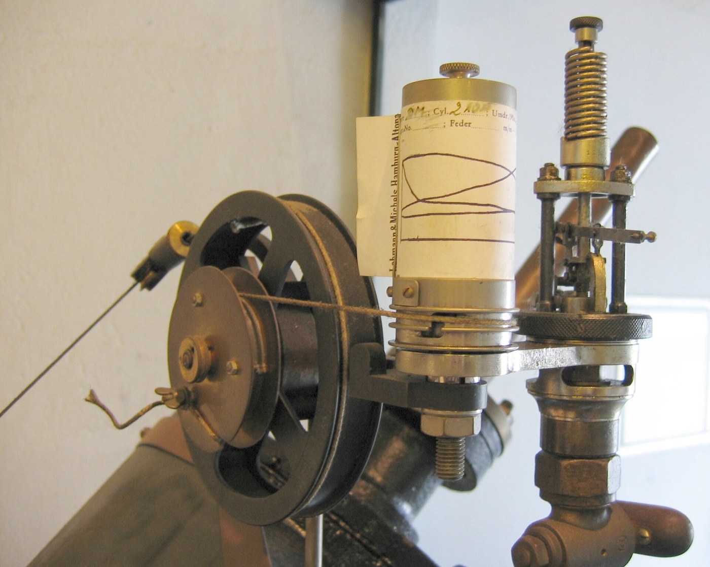


Watt Indicator Diagram
Amabwiriza
Build the pressure piston and its spring
Build the pressure piston and its spring
A small cylinder whose piston moves against a calibrated spring — pressure becomes displacement.
- Bore a cylinder 20 mm diameter and 60 mm long in aluminium bar.
- Turn a piston to fit closely, with an O-ring or a snug fit.
- Fit a compression spring above it, and a rod passing up out of the top.
- Calibrate: apply known pressures with a syringe or a water column and record the rod's travel at each.
- Plot pressure against displacement and confirm it is a straight line.
Spring choice sets the instrument's range. A stiff spring gives a small, hard-to-read trace on a high-pressure engine; a soft one bottoms out. Indicator springs were sold in graded sets and the operator chose one for the engine, marking the diagram with which spring was used — without that number the diagram cannot be interpreted at all.
Linearity is what makes the vertical axis a true pressure scale. A spring that stiffens as it compresses distorts the diagram in a way that is invisible on the paper and wrong in the area.Ibikoresho by'iyi ntambwe:
 Umurongo Uzengurutse wa Aluminiyumu1 igice
 Ikusanyirizo ry'Imizingo Ikandamizwa1 ikirundo
 Umwenda wa Musulini w'Ipamba1 metre
Ibikoresho bikenewe:
 Icyuma Cyivumbura Kidafite Insinga
 Ibyuma Byinshi byo Gucukura
 Amakariso Menshi
 Ifatiro ry'Ameza
 Ikigereranyo cya Digitale cy'Amasentimetero 6
Build the rotating paper drum
Build the rotating paper drum
The horizontal axis must follow the engine's piston, not the clock.
- Make a drum 60 mm diameter on a vertical spindle in 608 bearings.
- Fit a clip to hold a wrapped sheet of paper.
- Wind a cord around the drum, with a return spring so it rewinds.
- Take the cord's free end to a reduction linkage driven by the engine's crosshead.
- Check the drum rotates back and forth through about 270 degrees over the full stroke.
Position, not time, is the horizontal axis. This is what makes the diagram a pressure-volume plot rather than a pressure-time trace. Cylinder volume is proportional to piston position, so the enclosed area has units of pressure times volume — which is energy. Drive the drum from a clock and you would get a completely different and far less useful graph.
The reduction linkage matters because an engine's stroke is far longer than the drum's travel. Any slack or stretch in that cord shows up as a distorted diagram, which is why indicator cords were kept short and taut.Ibikoresho by'iyi ntambwe:
 Urupapuro rw'ibiti byometse1 urupapuro
 Bearing y'utubumbe2 ibiceIkusanyirizo ry'Imizingo Ikandamizwa1 ikirundo
 Uruziga Rurambuye8 ibice
 Umupira w'Impande Esheshatu4 ibice
Ibikoresho bikenewe:
Icyuma Cyivumbura Kidafite InsingaIbyuma Byinshi byo Gucukura Umucumita w'Imigororwa
 Imfunguzo Nyinshi z'Impande EsheshatuAmakariso MenshiIkigereranyo cya Digitale cy'Amasentimetero 6
Link the pencil with a straight-line motion
Link the pencil with a straight-line motion
The pencil must move in a straight line parallel to the drum's axis, and this is a familiar problem.
- Connect the piston rod to the pencil through a linkage that keeps the pencil travelling straight.
- Use a Watt's linkage or a simple parallel motion — the same problem solved in batch 68.
- Amplify the piston's travel by three or four times so the trace is readable.
- Set the pencil to bear lightly on the paper.
Watt used his own straight-line linkage here. A pencil swinging on a simple lever traces an arc, so equal pressures at different heights would land at different horizontal positions and skew the diagram. The same inventor's solution to the same geometric problem, applied twice in the same company — once to guide a piston rod on a beam engine, once to guide a pencil on an instrument.
Light pencil pressure. A pencil pressed hard adds friction to the pressure piston, which shows up as a diagram that is too small on the rising side and too large on the falling side — a hysteresis loop inside the real loop.Ibikoresho by'iyi ntambwe:
 Umurongo w'Aluminiyumu Urambuye1 igice
 Insimburangingo Ifite Umutwe Uzengurutse6 ibiceUruziga Rurambuye12 ibice
 Ecrou ifunga ifite umuzingo wa nayiloni6 ibice
 Amakaramu Menshi ya Girafite1 ikirundo
Ibikoresho bikenewe:
Icyuma Cyivumbura Kidafite InsingaIbyuma Byinshi byo GucukuraImfunguzo Nyinshi z'Impande EsheshatuAmakariso MenshiIkigereranyo cya Digitale cy'Amasentimetero 6 Ikigereranyo Gihuriweho
Take a diagram and measure its area
Take a diagram and measure its area
The area is the answer, and counting squares is how it was done for a century.
- Connect the instrument to a working air compressor cylinder or a hand-pumped model.
- Run it and let the pencil trace a full cycle.
- Transfer the loop to graph paper and count the squares inside it.
- Convert: area × spring scale × drum scale gives work per cycle.
- Multiply by cycles per minute for power.
Ibikoresho by'iyi ntambwe:
 Urupapuro rw'Imirongo1 pad
Ibikoresho bikenewe:
Ikigereranyo cya Digitale cy'Amasentimetero 6 Isaha yo GuhagarikaIkigereranyo Gihuriweho
The first self-recording instrument, and history
The first self-recording instrument, and history
John Southern, an engineer with Boulton and Watt, devised the indicator around 1796, building on a simple pressure gauge Watt had already used. The firm treated it as a trade secret for roughly two decades — it let them diagnose and improve engines in ways competitors simply could not, and the commercial advantage was real.
Two things make it historically significant. It is the first instrument that records its own measurement automatically, without an observer writing anything down — the ancestor of every chart recorder, oscilloscope and data logger since. And it produces a graph whose AREA is the quantity of interest, which is a genuinely sophisticated idea: the instrument performs an integration mechanically, decades before anyone would describe it that way.
Where it sits in this chain. The pitot tube converts velocity into pressure so it can be read. The Wedgwood pyrometer records a permanent effect to be read afterwards. The indicator goes further than both — it measures continuously while the process runs and writes the result down itself. That progression, from proxy to record to live self-recording signal, is the story of the whole batch.
Its honest limits: the moving parts have inertia, so at high engine speeds the pencil cannot keep up and the diagram is distorted — which is why indicators were fine on slow beam engines and problematic on fast ones. Friction in the mechanism opens a false loop. And it must be fitted to a tapping on the cylinder, so it can only be used on engines built to accept it.
Ibikoresho
13- Umwanya
- 1 ikirundoUmwanya
- 1 metreUmwanya
- 1 urupapuroUmwanya
- Umwanya
- 8 ibiceUmwanya
- 4 ibiceUmwanya
- Umwanya
- Umwanya
- 12 ibiceUmwanya
- Umwanya
- 1 ikirundoUmwanya
- Umwanya
Ibikoresho bikenewe
9- 1 vendor sell this, none ship to you yetUmwanya
- Umwanya
- Umwanya
- Umwanya
- Umwanya
- Umwanya
- Umwanya
Blueprint zijyanye
Izi blueprint zisangira ubumenyi — uburyo, ibikoresho cyangwa amahame

CC0 Umurenge rusange
Iyi blueprint yasohowe munsi ya CC0. Ushobora gukoporora, guhindura, gukwirakwiza no gukoresha nta kwemererwa.
Shyigikira Umuremyi ugura ibicuruzwa binyuze muri Blueprint ye Komisiyo y'Umuremyi byashyizweho n'Abacuruzi, cyangwa kora verisiyo nshya y'iyi Blueprint ukayinjiza nk'isano muri Blueprint yawe kugira ngo musangire inyungu.