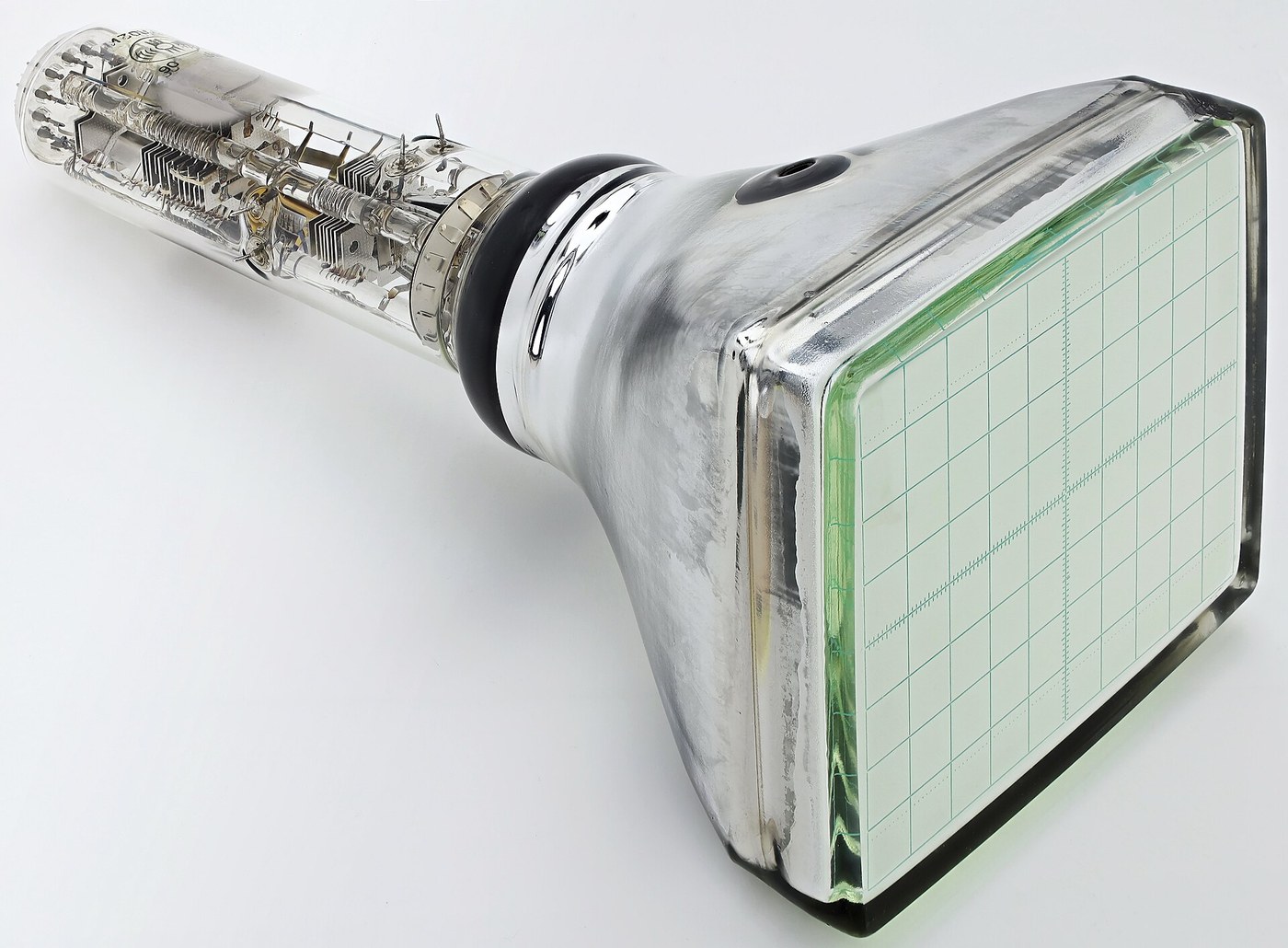


The Cathode-Ray Tube
التعليمات
Read the two hazards, which are unrelated to each other
Read the two hazards, which are unrelated to each other
A CRT is dangerous in two independent ways and neither protects you from the other.
- Implosion. The envelope holds a hard vacuum against full atmospheric pressure. A break does not throw glass outward, it collapses inward and then sprays fragments in every direction. Wear a face shield whenever a tube is exposed, handle it by the body and never by the neck, and never scratch or knock the glass.
- High voltage. The anode runs at several kilovolts, and the tube’s own internal capacitance stores that charge for a long time after power is removed. Always short the anode connection to chassis with an insulated lead before touching anything.
- Work with one hand behind your back, and never alone.
The stored-charge hazard is the one that catches people, because the set is switched off and everything looks safe. The aquadag coating on the tube and its earthed counterpart form a capacitor of a few nanofarads at several kilovolts, which is a genuinely dangerous amount of energy.
If you cannot meet these conditions, follow this blueprint on paper or with a salvaged working tube in its original chassis. Every principle below can be demonstrated on an intact commercial tube without ever opening the envelope.المواد لهذه الخطوة:
 أنبوب أشعّة مهبطية (مستعاد، صغير)1 قطعة
 سلك تفريغ عالي الجهد1 قطعة
الأدوات المطلوبة:
 درع للوجه
 نظارة أمان شفافة
 مجسّ راسم ذبذبات عالي الجهد
 مقياس متعدد رقمي بدرجة مختبرية
Make a beam and prove it is made of particles
Make a beam and prove it is made of particles
Establish what the beam actually is before steering it.
- Using a demonstration discharge tube, apply high voltage between cathode and anode and observe the glow.
- Place an object in the beam path and look for its shadow on the far wall.
- Bring a magnet near the tube and watch the beam bend.
- Note which way it bends relative to the field.
The sharp shadow proves the rays travel in straight lines; the magnetic deflection proves they are charged and moving; and the direction of the bend shows the charge is NEGATIVE. These three observations are exactly how the electron was identified, and you can reproduce all of them in an afternoon.
Historically this settled a genuine argument. Some physicists held that cathode rays were waves in the aether; the magnetic deflection is very hard to explain that way. J. J. Thomson went further in 1897 and measured the charge-to-mass ratio by balancing electric against magnetic deflection, finding a particle about two thousand times lighter than a hydrogen atom — the first subatomic particle anyone had found.المواد لهذه الخطوة:
أنبوب أشعّة مهبطية (مستعاد، صغير)1 قطعة طقم مغناطيسات نيوديميوم1 طقم
الأدوات المطلوبة:
 مصدر تغذية مختبري قابل للضبطمجسّ راسم ذبذبات عالي الجهدمقياس متعدد رقمي بدرجة مختبريةدرع للوجهنظارة أمان شفافة
Focus the beam with an electrostatic lens
Focus the beam with an electrostatic lens
A beam that spreads is useless. Focusing it uses optics made of voltage.
- Identify the electrode structure in the tube neck: cathode, control grid, and two or more anodes at different potentials.
- Vary the first anode voltage and watch the spot size on the screen.
- Find the setting that gives the smallest, sharpest spot.
- Now vary the control grid voltage and watch the BRIGHTNESS instead.
The region between two electrodes at different potentials bends electron paths exactly as a glass lens bends light, and the focal length depends on the voltage ratio. Adjusting focus is therefore an electrical operation with no moving parts — which is why the focus control on an oscilloscope is just a potentiometer.
Note the clean separation of duties: the grid controls how MANY electrons pass, the anodes control where they CONVERGE. Brightness and focus are independent, which is what makes the tube usable.
Reverse-engineering note: television tubes generally use magnetic focus and deflection coils around the neck rather than internal plates, because magnetic deflection achieves much wider angles — necessary for a short tube with a big screen. Oscilloscopes use electrostatic plates because they respond far faster. Same tube, opposite choice, and the reason is entirely about what each instrument needs.المواد لهذه الخطوة:
أنبوب أشعّة مهبطية (مستعاد، صغير)1 قطعة طقم مقاومات1 طقم
 مقياس جهد متغيّر2 قطع
الأدوات المطلوبة:
مصدر تغذية مختبري قابل للضبطمجسّ راسم ذبذبات عالي الجهدمقياس متعدد رقمي بدرجة مختبرية راسم إشارةدرع للوجهنظارة أمان شفافة
Deflect it in two axes and draw a Lissajous figure
Deflect it in two axes and draw a Lissajous figure
Two pairs of plates at right angles turn a spot into a display.
- Apply a slowly varying voltage to the horizontal plates and observe the spot sweep across.
- Apply a signal to the vertical plates and observe it move up and down.
- Now drive both from separate signal generators and vary their frequency ratio.
- Photograph the patterns at ratios of 1:1, 1:2 and 2:3.
Simple frequency ratios produce closed, stable figures; anything else produces a pattern that drifts and never closes. These are Lissajous figures, and before frequency counters existed they were the most precise way to compare two frequencies — you adjusted one until the figure stood still, and then you knew the ratio exactly.
This is a nice example of a measurement technique that vanished not because it was bad but because something cheaper arrived. A digital counter is more convenient; a Lissajous figure shows you phase as well as frequency, at a glance, with no numbers at all. Both are still true.المواد لهذه الخطوة:
طقم مقاومات1 طقم طقم مكثّفات1 طقم
 لوح مثقّب للتنفيذ1 قطعة
 سلك لحام 63/37 بقلب صمغي1 reel
الأدوات المطلوبة:
 مولّد إشارة
 مولّد إشاراتمصدر تغذية مختبري قابل للضبطراسم إشارةمجسّ راسم ذبذبات عالي الجهدمقياس متعدد رقمي بدرجة مختبريةدرع للوجهنظارة أمان شفافة
Add a timebase and make it an oscilloscope
Add a timebase and make it an oscilloscope
One specific horizontal waveform turns the tube into the most useful instrument in electronics.
- Build a sawtooth generator: a capacitor charged through a constant current and discharged abruptly.
- Drive the horizontal plates with it, so the spot sweeps steadily left to right and then flies back.
- Apply the signal under test to the vertical plates.
- Adjust the sawtooth frequency until the display stands still.
When the sweep period is an exact multiple of the signal period the trace repeats identically and appears frozen; otherwise it crawls across the screen. That is the whole idea — the horizontal axis has become TIME, and a voltage that varies too fast to imagine is now a stationary shape you can measure with a ruler.
Making the display stand still by hand is tiresome, and the fix is triggering: instead of running the sweep continuously, start it at the moment the input crosses a chosen level. Every sweep then begins at the same point on the waveform and the picture is stable regardless of frequency.
The flyback must be fast and blanked — the beam is switched off during the return, or you would see a bright line running backwards across every trace. That blanking pulse is why the control grid has its own connection, and it is the same mechanism television later used between lines and between frames.المواد لهذه الخطوة:
طقم مكثّفات1 طقمطقم مقاومات1 طقم تشكيلة ترانزستورات1 طقم
الأدوات المطلوبة:
راسم إشارةمولّد إشارةمصدر تغذية مختبري قابل للضبطمقياس متعدد رقمي بدرجة مختبرية محطة لحاممجسّ راسم ذبذبات عالي الجهددرع للوجهنظارة أمان شفافة
المواد
9- عنصر نائب
- 1 قطعةعنصر نائب
- عنصر نائب
- عنصر نائب
- عنصر نائب
- 1 طقمعنصر نائب
- 1 قطعةعنصر نائب
- 1 reelعنصر نائب
- 1 طقمعنصر نائب
الأدوات المطلوبة
9- عنصر نائب
- عنصر نائب
- عنصر نائب
- عنصر نائب
- عنصر نائب
- عنصر نائب
- عنصر نائب
- عنصر نائب
- عنصر نائب
المخططات ذات الصلة
هذه المخططات تشارك المعرفة مع هذا — التقنيات والمواد والمبادئ


CC0 ملكية عامة
هذا المخطط مُصدر بموجب CC0. يحق لك نسخه وتعديله وتوزيعه واستخدامه لأي غرض، دون طلب إذن.
ادعم الصانع بشراء منتجات عبر مخططه حيث يكسب عمولة الصانع يحددها البائعون، أو أنشئ نسخة جديدة من هذا المخطط وضمّنه كرابط في مخططك لمشاركة الإيرادات.