التعاون
فنون
الجمال والعناية
حِرَف
الثقافة والتاريخ
ترفيه
البيئة
الطعام والمشروبات
الهندسة العكسية
العلوم
رياضة
التقنية
الأجهزة القابلة للارتداء
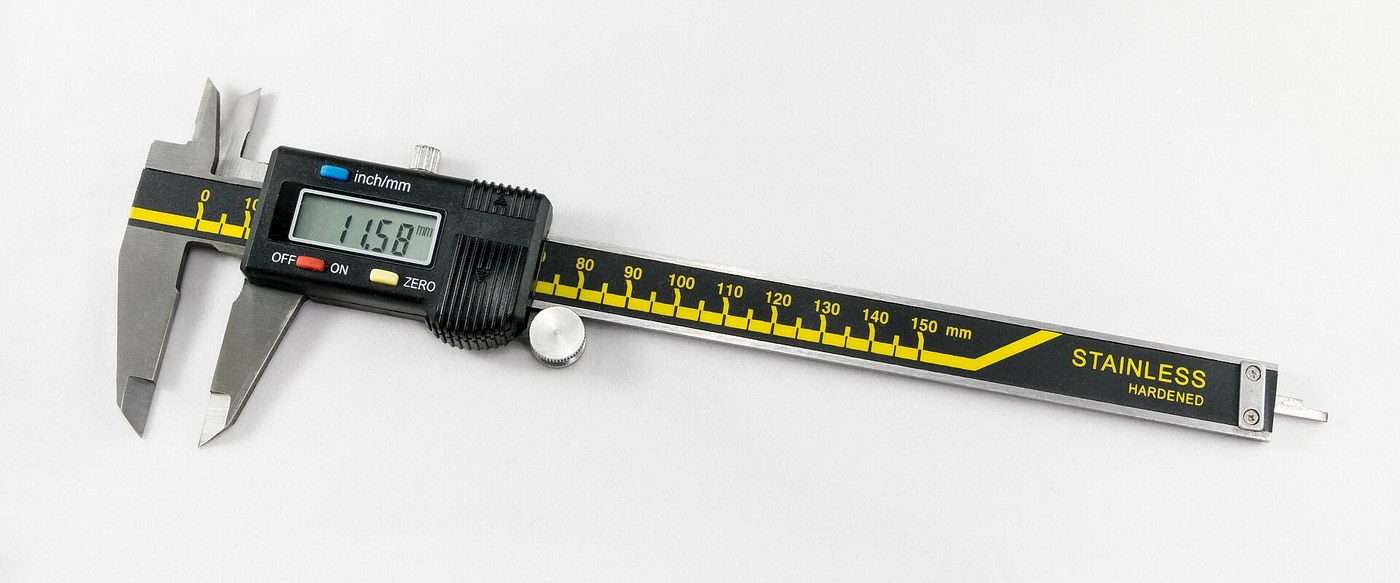


Digital Caliper: Capacitive Scale and Slider with Two-Chip Electronics (Baxter and Buehler, Starrett, 1986)
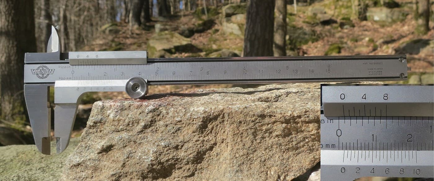
A six-inch caliper that reads out on a display. Under the slide, a strip of etched copper bars runs along the beam. Electrodes on the slider pass a signal through the bars by capacitance, and the slider's electronics count the bars crossed and work out the position in between.
Result: a digital caliper reading in inches or millimetres, repeatable to a ten-thousandth of an inch, with floating zero, peak hold and high/low limits. It runs on two 1.5 V cells at 10-50 microamps.
Source: L. K. Baxter and R. J. Buehler (L. S. Starrett Co.), US Patent 4,586,260 (1986). Unknown: the metal of the beam, slide and rod, their dimensions, the processor's program, and how the chips and display are made. Ours: the etchant, photoresist and glue. Picture: Wikimedia Commons.
متقدم
2 days
التعليمات
1
1
Etch the scale
Etch the scale
Etch the scale pattern onto a strip of copper-clad epoxy fibreglass with photoresist and etchant. Each copper bar is 0.40 inch long, with a wider centre 0.12 inch long and two ends 0.14 inch long. Space the bars on 0.05 inch centres: the centres sit 0.004 inch apart, the ends 0.025 inch apart. Run the pattern the full length of the scale. Ours: dry film resist and ferric chloride.
المواد لهذه الخطوة:
 لوح دارة مطبوعة خام (مكسوّ بالنحاس)1 strip, length of the beam
الأدوات المطلوبة:
 مقاوم ضوئي بغشاء جافّ
 محلول كلوريد الحديد الثلاثي
 قفازات مقاومة للكيماويات
2
2
Fix the scale into the beam
Fix the scale into the beam
The beam is a metal bar with the fixed outside and inside jaws at one end, a wide shallow channel in its face and a second channel along its back. Fix the scale permanently into the face channel, copper up. The patent allows etching before or after this step. Not given: the metal, the dimensions and how the scale is fixed. Ours: epoxy.
المواد لهذه الخطوة:
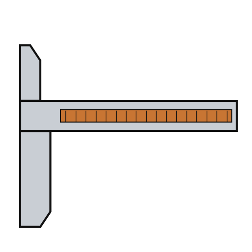 ساق القدمة1 with integral jaws
 إيبوكسي ثنائي المكوّن1 a little
الأدوات المطلوبة:
 أبعاد غير معروفة
3
3
Fit the parts to the circuit
Fit the parts to the circuit
The circuit is one folded piece: a double-sided slider board joined by a flexible hinge to a circuit board. Its bottom face has two pickup electrodes, 0.750 x 0.110 inch and 0.0625 inch apart. On each side of them is an interdigitated transmitter array: fingers 0.115 inch long on 0.025 inch spacing, opening to 0.0375 inch at the centre. On the circuit board, solder or wire-bond the two chips: an NEC uPD7503 3 V processor (768 bits RAM, 2 kB ROM) and a CMOS gate array. Then fit the LCD, the 100 kHz crystal, the integrating capacitor and the MODE and SET buttons. Not given: the processor's program. Ours: a capacitor from a kit.
المواد لهذه الخطوة:
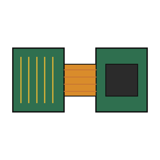 لوحة دارة صلبة مرنة1 slider board + circuit board
 دارة متكاملة2 uPD7503 CPU, CMOS gate array
 شاشة بلورات سائلة مقطعية1 5 digits
 بلورة كوارتز1 100 kHz
 طقم مكثّفات1 one integrating capacitor
 زر ضغط2 MODE, SET
 سلك لحام1 a little
الأدوات المطلوبة:
 كاوية لحام
4
4
Build the slide
Build the slide
The slide frame wraps the back and edges of the beam and carries the movable jaws. Fix it to the depth rod, which runs in the back channel of the beam; the rod's free end is the depth gauge. Put the moulded plastic housing between the frame ends. Fasten two metal wear strips under the slider board, one on each side of the scale. They ride on the beam and connect the board's copper to it. Not given: the metal and sizes.
المواد لهذه الخطوة:
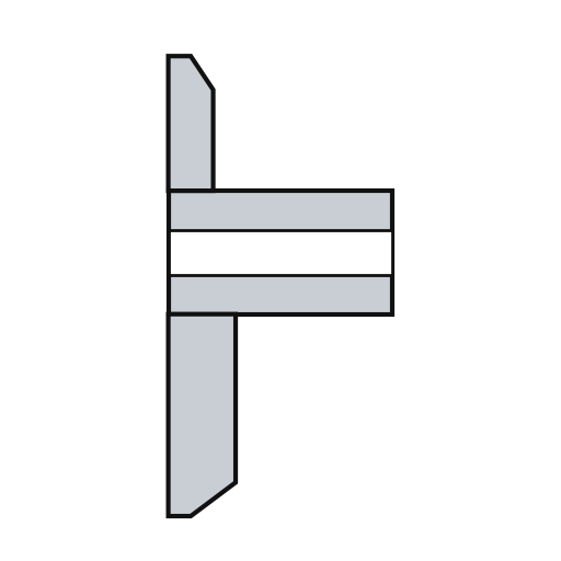 إطار المنزلقة1 with jaws
 معدن غير معروف1 depth rod and two wear strips
 غلاف المنزلقة1 قطعة
الأدوات المطلوبة:
أبعاد غير معروفة طقم مفكّات دقيقة
5
5
Assemble and check
Assemble and check
Fold the circuit into the housing recess, slider board facing the scale, and screw it to the frame. The electrodes must lie parallel to the scale bars at every point of travel. Put the two 1.5 V cells (the patent says 'zinc oxide') in the battery pockets of the circuit. The display shows five digits, a ten-thousandths bar graph, a minus sign and 'mm', plus PEAK, LOW, HIGH and LIMIT. Ours: check the reading against a vernier caliper.
المواد لهذه الخطوة:
 براغي آلية2 قطع
 بطارية زر 1.5 فولت2 قطع
الأدوات المطلوبة:
طقم مفكّات دقيقة قدمة ورنية
المواد
15- 1 strip, length of the beamعنصر نائب
- 1 with integral jawsعنصر نائب
- 1 a littleعنصر نائب
- 1 slider board + circuit boardعنصر نائب
- 2 uPD7503 CPU, CMOS gate arrayعنصر نائب
- 1 5 digitsعنصر نائب
- 1 100 kHzعنصر نائب
- 1 one integrating capacitorعنصر نائب
- عنصر نائب
- 1 a littleعنصر نائب
- 1 with jawsعنصر نائب
- 1 depth rod and two wear stripsعنصر نائب
- 1 قطعةعنصر نائب
- 2 قطععنصر نائب
- 2 قطععنصر نائب
الأدوات المطلوبة
7- عنصر نائب
- عنصر نائب
- عنصر نائب
- عنصر نائب
- 2 vendors sell this, none ship to you yetعنصر نائب
- عنصر نائب
- عنصر نائب
مواد المخططات المرتبطة

هذا المخطط يصنع

المخططات ذات الصلة
هذه المخططات تشارك المعرفة مع هذا — التقنيات والمواد والمبادئ
CC0 ملكية عامة
هذا المخطط مُصدر بموجب CC0. يحق لك نسخه وتعديله وتوزيعه واستخدامه لأي غرض، دون طلب إذن.
ادعم الصانع بشراء منتجات عبر مخططه حيث يكسب عمولة الصانع يحددها البائعون، أو أنشئ نسخة جديدة من هذا المخطط وضمّنه كرابط في مخططك لمشاركة الإيرادات.