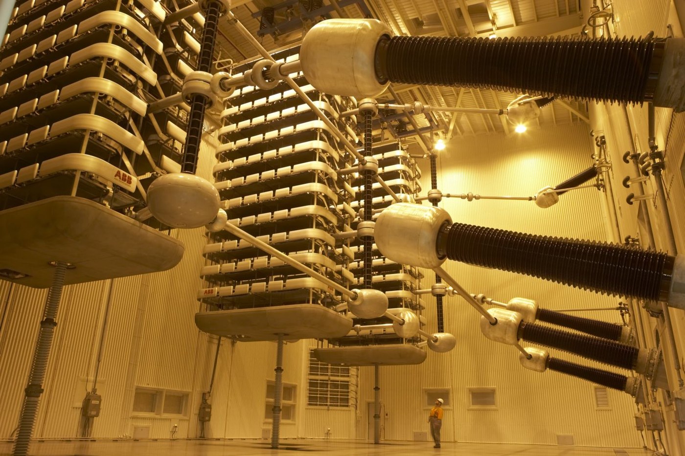

High-Voltage Direct Current Transmission
التعليمات
Measure the charging current that kills long AC cables
Measure the charging current that kills long AC cables
Do not take the argument on trust. The number is easy to measure and startling once you have it.
- Take a long coil of coaxial cable — fifty metres or more — and leave the far end completely open circuit.
- Measure the capacitance between inner conductor and screen with an LCR meter, and divide by the length to get capacitance per metre.
- Apply a low-voltage AC signal at 50 Hz to the near end, still with the far end open, and measure the current flowing in.
- Now apply DC of the same voltage and measure the steady current.
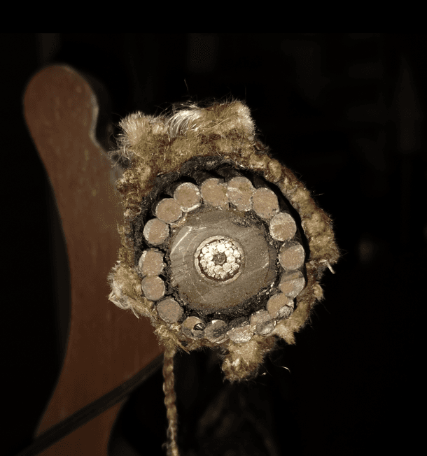
The AC case draws current into an open circuit; the DC case draws essentially nothing once the initial charge has flowed. That is the whole argument in miniature. Now scale it: a typical submarine power cable runs around 200 nanofarads per kilometre, so a hundred kilometres is roughly 20 microfarads, and at 132 kV and 50 Hz that draws on the order of 800 amperes of pure charging current before a single watt reaches the far end.
Overhead lines suffer far less because the conductors are metres apart in air rather than millimetres apart in oiled paper, so the capacitance per kilometre is perhaps a fiftieth of a cable’s. That is why the AC limit is a few hundred kilometres overhead and under a hundred submarine. The reason DC returned is not efficiency in general — it is that capacitance is a problem only for alternating current.
Compensation can extend an AC cable’s reach by installing shunt reactors that absorb the charging current, but a submarine cable has nowhere to put them. You cannot build a compensating station in the middle of the Baltic.المواد لهذه الخطوة:
 كبل محوري (RG-58)1 reel
الأدوات المطلوبة:
 مقياس LCR مكتبي
 مقياس متعدد رقمي بدرجة مختبرية
 راسم إشارة
 مشبك قياس التيار AC/DC 600 أمبير
 مولّد إشارات
 نظارة أمان شفافة
Build a six-pulse bridge and see why three phases matter
Build a six-pulse bridge and see why three phases matter
Rectification at bench scale, with the same topology used at gigawatt scale.
- Build a single-phase bridge from four diodes and observe the output on the oscilloscope.
- Now build a three-phase bridge from six diodes, fed from a three-phase source or a simulated one, and observe again.
- Measure the ripple amplitude as a percentage of the mean in each case, and note the ripple frequency.
The single-phase bridge gives output touching zero twice a cycle; the six-pulse bridge never comes close to zero and ripples at six times the supply frequency, at only a few percent of the mean. Six pulses per cycle means the smoothing reactor has six times less time to do six times less work — smaller, cheaper, lighter.
The reason is geometric rather than electrical. Three phases spaced 120 degrees apart mean that at any instant one is near its peak; the bridge simply connects the load to whichever pair currently has the greatest difference between them. Rectification here is not really about converting a waveform, it is about always selecting the best available pair of terminals.
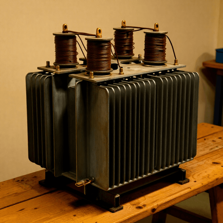
Real HVDC converters go to twelve pulse by feeding two six-pulse bridges from transformers wound star and delta, so their outputs are 30 degrees apart. Ripple drops again and, more importantly, the fifth and seventh harmonics on the AC side cancel — which is what step 4 is about.المواد لهذه الخطوة:
 طقم قناطر ديودات مقوِّمة1 طقم
 ديود تقويم 1N40071 عبوة
 سلك نحاسي مطلي بالمينا10 m
الأدوات المطلوبة:
راسم إشارةمقياس متعدد رقمي بدرجة مختبريةمولّد إشارات مصدر تغذية مختبري قابل للضبط
 كمّاشة كبس الأطرافنظارة أمان شفافة
Control the firing angle, and discover the converter can run backwards
Control the firing angle, and discover the converter can run backwards
Replace the diodes with switches you can command, and a rectifier becomes something much more useful.
- Substitute thyristors for the diodes and drive their gates from a controller that can delay firing relative to the natural commutation instant.
- Start with zero delay and confirm the output matches the diode bridge.
- Increase the delay angle progressively and plot mean output voltage against it.
- Take the delay past ninety degrees and observe the sign of the mean output voltage.
Beyond ninety degrees the mean DC voltage goes negative, and with current still flowing in the same direction the converter is now taking power out of the DC side and delivering it to the AC side. The same hardware is a rectifier below ninety degrees and an inverter above it, with nothing changed but timing. That is why an HVDC link needs no separate machinery at each end and why power flow can be reversed by control action alone.
The delay angle is also the control handle for everything else. Power transfer is set by the difference between the two ends’ DC voltages, so a controller at one end regulates current while the other regulates voltage, and the link’s throughput can be commanded directly. An AC interconnector has no such handle — power flows wherever the impedances send it.
Note the constraint that comes with it: a thyristor can be told when to start conducting but not when to stop. It turns off only when the circuit brings its current to zero, which for this converter means relying on the AC voltage to commutate it. The whole scheme therefore depends on a healthy AC system at both ends — line-commutated conversion. Modern voltage-source converters use IGBTs, which can be switched off on command, and consequently can feed a dead network and start it from nothing.المواد لهذه الخطوة:
 ثايرستور (SCR)6 قطع
 لوحة قيادة البوّابة بمقرن ضوئي1 قطعة
الأدوات المطلوبة:
راسم إشارةمولّد إشاراتمقياس متعدد رقمي بدرجة مختبريةمصدر تغذية مختبري قابل للضبطمشبك قياس التيار AC/DC 600 أمبيرنظارة أمان شفافةFind the harmonics you just created, and filter them
Find the harmonics you just created, and filter them
A converter is a nonlinear load, and nonlinear loads pollute the system that feeds them.
- Put the oscilloscope on the AC-side current drawn by your six-pulse bridge, not on the DC output.
- Run an FFT on that current.
- Identify which harmonics are present and which are absent.
- Add a series LC branch tuned to the largest one and repeat the measurement.
A six-pulse converter draws current containing the fifth, seventh, eleventh and thirteenth harmonics but not the third or the ninth. The pattern is not arbitrary: a p-pulse converter produces harmonics at orders p times k plus or minus one. For six pulse that is 5, 7, 11, 13; for twelve pulse the fifth and seventh vanish and the lowest survivor is the eleventh, which is both smaller and easier to filter.
This is why a real converter station is mostly not converter. Rows of tuned filter banks handle the AC-side harmonics, smoothing reactors handle the DC side, and the filters double as the source of reactive power the converter consumes — a line-commutated converter absorbs reactive power roughly half its real power rating, and something has to supply it.
Harmonics are not an accounting problem, they are a physical one. They heat transformers and motors, overload capacitor banks that look like a short circuit at high frequency, and interfere with telephone and signalling circuits — which is how the problem was usually discovered, by someone complaining about noise on a line miles away.المواد لهذه الخطوة:
سلك نحاسي مطلي بالمينا15 m تشكيلة مكثّفات غشائية (لقدرة عالية)1 طقم
 قلب فرّيتي حلقي2 قطع
الأدوات المطلوبة:
راسم إشارة محلّل طيف / برنامج FFTمشبك قياس التيار AC/DC 600 أمبيرمقياس متعدد رقمي بدرجة مختبريةمقياس LCR مكتبينظارة أمان شفافة
Run it as a monopole with sea return, as Gotland did
Run it as a monopole with sea return, as Gotland did
The 1954 link used one cable, not two, and the sea completed the circuit.
- Sketch the Gotland scheme: a converter station at each end, a single 100 km submarine conductor, and an electrode in the sea at each end forming the return path.
- Work out what halving the number of cables saves, and what it costs.
- Consider what happens to a steel structure buried near one of those electrodes.
Sea return works because seawater is a good conductor and the ocean is very large, so the return path has negligible resistance and the scheme needs only one expensive cable. For a link whose dominant cost is the cable, that is close to halving the capital cost of the project.
The costs are real and were understood at the time. A steady direct current in the ground drives electrolytic corrosion of buried metalwork near the electrodes — pipelines, cable sheaths, harbour piling — so the electrodes are sited well away from infrastructure and often several kilometres offshore. The steady current also deflects magnetic compasses nearby, which matters in a shipping lane. Later schemes commonly use a metallic return or a full bipole with two conductors at opposite polarity, where the ground carries only the small imbalance and either pole can keep running alone at half power if the other fails.
Gotland ran at 100 kV and 20 MW using mercury arc valves developed by Uno Lamm at ASEA, and it is the direct ancestor of every HVDC link since — including the multi-gigawatt lines that now move hydro power thousands of kilometres across China and Brazil, and the interconnectors that let neighbouring grids trade power without having to run in synchronism with one another. That last capability is quietly the most valuable one: two AC systems can only be joined directly if they agree on phase forever, whereas a DC link joins them while letting each keep its own time.المواد لهذه الخطوة:
 صفيحة نحاس2 أوراق
 كتلة غرافيت2 قطع
 كلوريد الصوديوم (ملح)1 box
الأدوات المطلوبة:
مقياس متعدد رقمي بدرجة مختبريةمشبك قياس التيار AC/DC 600 أمبير جهاز قياس مقاومة العزل
 كاميرا تصوير حراريراسم إشارةنظارة أمان شفافة
المواد
11- 1 reelعنصر نائب
- عنصر نائب
- 1 عبوةعنصر نائب
- عنصر نائب
- 6 قطععنصر نائب
- عنصر نائب
- عنصر نائب
- 2 قطععنصر نائب
- 2 أوراقعنصر نائب
- 2 قطععنصر نائب
- عنصر نائب
الأدوات المطلوبة
11- عنصر نائب
- عنصر نائب
- عنصر نائب
- عنصر نائب
- عنصر نائب
- عنصر نائب
- عنصر نائب
- عنصر نائب
- عنصر نائب
- عنصر نائب
- عنصر نائب
المخططات ذات الصلة
هذه المخططات تشارك المعرفة مع هذا — التقنيات والمواد والمبادئ


CC0 ملكية عامة
هذا المخطط مُصدر بموجب CC0. يحق لك نسخه وتعديله وتوزيعه واستخدامه لأي غرض، دون طلب إذن.
ادعم الصانع بشراء منتجات عبر مخططه حيث يكسب عمولة الصانع يحددها البائعون، أو أنشئ نسخة جديدة من هذا المخطط وضمّنه كرابط في مخططك لمشاركة الإيرادات.