فنون
الجمال والعناية
حِرَف
الثقافة والتاريخ
ترفيه
البيئة
الطعام والمشروبات
الهندسة العكسية
العلوم
رياضة
التقنية
الأجهزة القابلة للارتداء
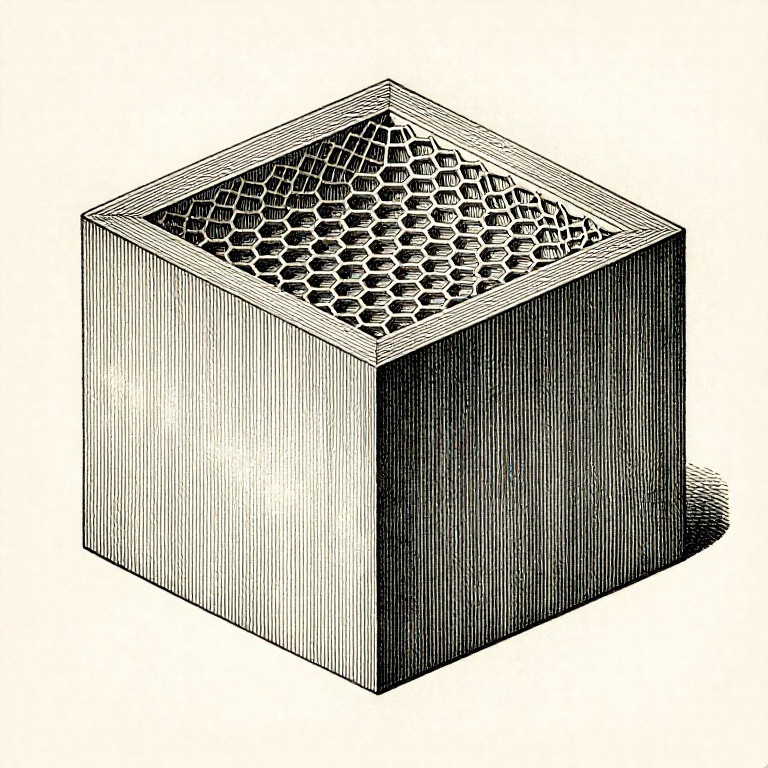


Walls and Infill: Strength Comes From the Outside, Not the Middle
The usual response to a part that broke is to raise the infill. It is almost always the wrong lever: for a part in bending, the material near the surface does most of the work and the material in the middle does almost none.
That is not a printing fact, it is geometry. Bending stiffness depends on how far the material sits from the neutral axis — so a wall at the outside is worth many times an equal weight of plastic in the centre.
Which makes WALL COUNT the setting that matters. Going from two walls to four typically does more for strength than going from 20% infill to 60%, and costs less time and less filament.
متوسط
3 hours
التعليمات
1
1
Walls against infill, in numbers
Walls against infill, in numbers
جارٍ تحميل دفتر Jupyter…
المواد لهذه الخطوة:
 خيط الطباعة ثلاثية الأبعاد (PLA)1 قطعة
الأدوات المطلوبة:
 حاسوب مكتبي
 برنامج تقطيع ملفات 3MF
 قدمة رقمية 6 بوصات
2
2
Make wall thickness a multiple of the line width
Make wall thickness a multiple of the line width
A wall 1.0 mm thick printed with a 0.42 mm line cannot be made of whole lines. The slicer either leaves a gap in the middle or over-extrudes to fill it, and both are weaker than a wall that is an exact number of lines.
So design walls at multiples of the line width: 0.84 mm for two lines, 1.26 for three, 1.68 for four. It is not fussiness — it is the difference between a wall that is solid and one with a void running through it.
Modern slicers handle odd thicknesses much better than they used to, varying the line width to suit. It is still worth designing to the grid where you can, and it is worth knowing this is why a 1 mm wall sometimes prints badly.
المواد لهذه الخطوة:
خيط الطباعة ثلاثية الأبعاد (PLA)1 قطعةالأدوات المطلوبة:
برنامج تقطيع ملفات 3MFحاسوب مكتبي طقم فوّهات لطابعة ثلاثية الأبعاد
3
3
Top and bottom layers, and why the top looks rough
Top and bottom layers, and why the top looks rough
The top surface is printed over infill, which is mostly air. Too few solid layers and the top sags into the gaps — the 'pillowing' that makes a top face look dimpled.
Four to five solid top layers is a normal starting point, and more infill helps by giving them less distance to bridge. That is one of the few cases where raising infill is the right answer, and it is about surface quality rather than strength.
The bottom needs solid layers too, and for a different reason: they are what the part stands on and what a screw head bears against. A part with one bottom layer tears through if anything is bolted to it.
المواد لهذه الخطوة:
خيط الطباعة ثلاثية الأبعاد (PLA)1 قطعةالأدوات المطلوبة:
برنامج تقطيع ملفات 3MF عدسة صائغ
 طابعة ثلاثية الأبعاد بالخيط (FDM)
4
4
Infill pattern matters less than people think
Infill pattern matters less than people think
Gyroid, cubic, grid, triangular — the differences between patterns at the same percentage are small compared with the difference between two walls and four. Choosing a pattern is a late optimisation.
Where it does matter: GYROID is isotropic and prints without the nozzle crossing its own path, which makes it quiet and good for flexible parts. GRID is fast but the nozzle crosses itself every layer, which can knock the part. TRIANGULAR is strong in plane and used where the load is known.
Pick one, use it consistently, and change the wall count instead. That is the change-one-thing-at-a-time rule applied to a slicer: a hundred settings are available and about four of them matter.
المواد لهذه الخطوة:
خيط الطباعة ثلاثية الأبعاد (PLA)1 قطعةالأدوات المطلوبة:
برنامج تقطيع ملفات 3MFحاسوب مكتبيالمخططات ذات الصلة
هذه المخططات تشارك المعرفة مع هذا — التقنيات والمواد والمبادئ


CC0 ملكية عامة
هذا المخطط مُصدر بموجب CC0. يحق لك نسخه وتعديله وتوزيعه واستخدامه لأي غرض، دون طلب إذن.
ادعم الصانع بشراء منتجات عبر مخططه حيث يكسب عمولة الصانع يحددها البائعون، أو أنشئ نسخة جديدة من هذا المخطط وضمّنه كرابط في مخططك لمشاركة الإيرادات.