ART
BEAUTY & WELLNESS
CRAFT
CULTURE & HISTORY
ENTERTAINMENT
ENVIRONMENT
FOOD & DRINKS
REVERSE ENGINEERING
SCIENCES
SPORTS
TECHNOLOGY
WEARABLES
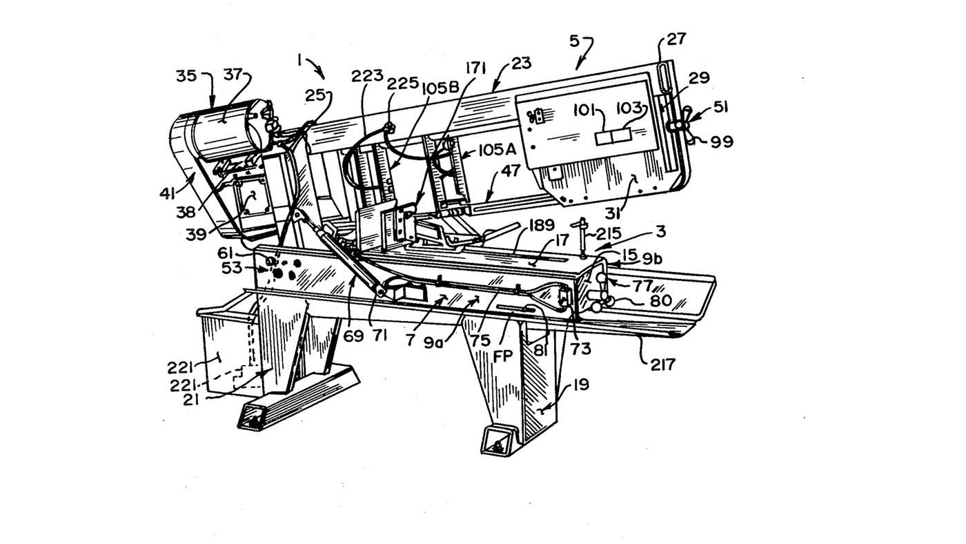


Metal Band Saw: Horizontal Saw on a Welded Steel Frame
Curtis Eccardt's horizontal power band saw (Emerson Electric, US 4,364,294, 1982), built from welded steel channel and tube instead of iron castings to cut its cost. The saw head swings down on trunnions over the bed; a hydraulic cylinder with a valve sets how fast it feeds, a spring counterbalances it, and a spring tensioner shows the blade tension on a scale. Two guides with rollers twist the blade's lower run 90° so its teeth face down into the work, and carbide inserts hold it there.
The patent gives no sizes, speeds or ratings; the welder and wrenches are ours. The picture: the patent's Fig. 1.
Advanced
4 days
Instructions
1
1
Weld the bed
Weld the bed
Stand two steel channels (9a, 9b) parallel, webs upright and flanges facing in, and weld gussets (15) between their webs. Bolt a bed plate (17) across the top flanges as the work surface. Ours: MIG welder, drill press for the bolt holes.
Materials for this step:
 Steel Channel Section2 pieces
 Mild Steel Plate1 piece
 Hex Bolt - Grade 8.81 piece
Tools needed:
 MIG Welder
 Drill Press
 Adjustable Wrench
2
2
Weld and bolt on the legs
Weld and bolt on the legs
Weld formed sheet-steel legs onto horizontal floor members to make front and rear leg weldments (19, 21), and bolt them under the bed.
Materials for this step:
 Steel Sheet1 piece
 Steel Tubing1 pieceHex Bolt - Grade 8.81 piece
Tools needed:
MIG WelderAdjustable Wrench3
3
Weld the head
Weld the head
Weld a head post (25) of square or rectangular steel tube square to a head beam (27) of rectangular tube. Weld a bracket leg (29) down from the beam's outer end, and fix support plates at both ends (31, 33).
Materials for this step:
Steel Tubing1 pieceMild Steel Plate1 pieceTools needed:
MIG Welder4
4
Fit the trunnions and align the pivot
Fit the trunnions and align the pivot
Fix a shaft through the head post with its ends out as trunnions (55a, 55b), in bushings in two bearing blocks (59a, 59b) bolted inside the channel webs. Each block has one close-fit bolt hole and three oversize ones: shift the blocks until the pivot is parallel to the bed plate, then torque the bolts. A set screw (67) takes out end play.
Materials for this step:
 Steel Shaft1 piece
 Metal Bushing2 pieces
 Bearing Block2 piecesHex Bolt - Grade 8.88 pieces
 Cup Point Set Screw1 piece
Tools needed:
Drill Press Torque Wrench
5
5
Mount motor, belt drive and gearbox
Mount motor, belt drive and gearbox
Mount the electric motor (37) on a plate (38) pivoted on the head beam, and couple it by a multi-speed belt and pulleys (41) to a gearbox (39). Fit the drive wheel (43) on the gearbox output shaft.
Materials for this step:
 Electric Motor1 pieceMild Steel Plate1 piece
 Drive Belt1 piece
 Pulley1 piece
 Gearbox1 piece
 Band Saw Wheel1 piece
Tools needed:
Adjustable Wrench6
6
Build the idler tensioner
Build the idler tensioner
Weld an idler yoke (87) of rolled steel plate, pivot it on the head beam with a pin (89), and cantilever the idler axle from it with the idler wheel (45) on bearings (85). A threaded rod (91) pulls the yoke through a coil spring (93) held between compression plates and a U-bolt (97); a knob (99) turns the rod. An indicator (101) on the spring reads the tension on a scale (103).
Materials for this step:
Mild Steel Plate1 piece Steel Pin1 pieceSteel Shaft1 pieceBand Saw Wheel1 piece
 Ball Bearing1 piece
 Threaded Rod1 piece
 Coil Spring1 piece
 U-Bolt1 piece
 Control Knob1 piece
Tools needed:
MIG WelderAdjustable Wrench7
7
Build the two blade guides
Build the two blade guides
In each guide channel (111) mount two guide rollers (115a, 115b) on ball bearings on eccentric bushings, one fixed and one adjusted to the blade thickness. Add a carbide thrust insert (133) on the blade's back edge and two carbide side inserts (137a fixed, 137b on a sprung swing bracket set by a bolt and knob). Clamp the guides on two bar tracks (107).
Materials for this step:
 Guide Roller4 piecesBall Bearing4 pieces
 Eccentric Bushing4 pieces
 Carbide Insert6 piecesCoil Spring2 piecesControl Knob2 piecesSteel Tubing1 piece
Tools needed:
Adjustable Wrench8
8
Fit the blade and set the tension
Fit the blade and set the tension
By hand, run the endless blade (47) round the drive and idler wheels and through both guides; the rollers twist its lower run about 90° so the teeth face down. Turn the tension knob until the scale shows the tension you want.
Materials for this step:
 Band Saw Blade1 piece
9
9
Fit the feed cylinder and counterbalance
Fit the feed cylinder and counterbalance
Connect a hydraulic cylinder (71) between bed channel and head post above the trunnions, filled with oil and piped through tubing (75) to a control valve (73): the valve sets the feed rate and, closed, holds the head. Fit a coil spring (78) on a threaded linkage (79) between an end gusset and the head post below the trunnions, adjusted by a knob (80), to counterbalance the head.
Materials for this step:
 Hydraulic Cylinder1 piece
 Hydraulic Oil1 batch
 Hydraulic Tubing1 piece
 Flow Control Valve1 pieceCoil Spring1 pieceThreaded Rod1 pieceControl Knob1 piece
Tools needed:
Adjustable Wrench10
10
Bolt on the vice
Bolt on the vice
Bolt the quick-acting vice to the bed plate to clamp the work square under the blade.
Materials for this step:
 Machine Vice1 pieceHex Bolt - Grade 8.81 piece
Tools needed:
Adjustable WrenchMaterials
29- 2 piecesPlaceholder
- 1 piecePlaceholder
- 11 piecesPlaceholder
- 1 piecePlaceholder
- 1 piecePlaceholder
- 1 piecePlaceholder
- 2 piecesPlaceholder
- 2 piecesPlaceholder
- 1 piecePlaceholder
- 1 piecePlaceholder
- 1 piecePlaceholder
- 1 piecePlaceholder
- 1 piecePlaceholder
- 1 piecePlaceholder
- 1 piecePlaceholder
- Placeholder
- 1 piecePlaceholder
- 4 piecesPlaceholder
- 1 piecePlaceholder
- Placeholder
- 4 piecesPlaceholder
- 4 piecesPlaceholder
- 6 piecesPlaceholder
- 1 piecePlaceholder
- 1 piecePlaceholder
- 1 batchPlaceholder
- 1 piecePlaceholder
- 1 piecePlaceholder
- 1 piecePlaceholder
CC0 Public Domain
This blueprint is released under CC0. You are free to copy, modify, distribute, and use this work for any purpose, without asking permission.
Support the Maker by purchasing products through their Blueprint where they earn a Maker Commission set by Vendors, or create a new iteration of this Blueprint and include it as a connection in your own Blueprint to share revenue.