ศิลปะ
ความงามและสุขภาพ
งานฝีมือ
วัฒนธรรมและประวัติศาสตร์
ความบันเทิง
สิ่งแวดล้อม
อาหารและเครื่องดื่ม
วิศวกรรมย้อนรอย
วิทยาศาสตร์
กีฬา
เทคโนโลยี
อุปกรณ์สวมใส่
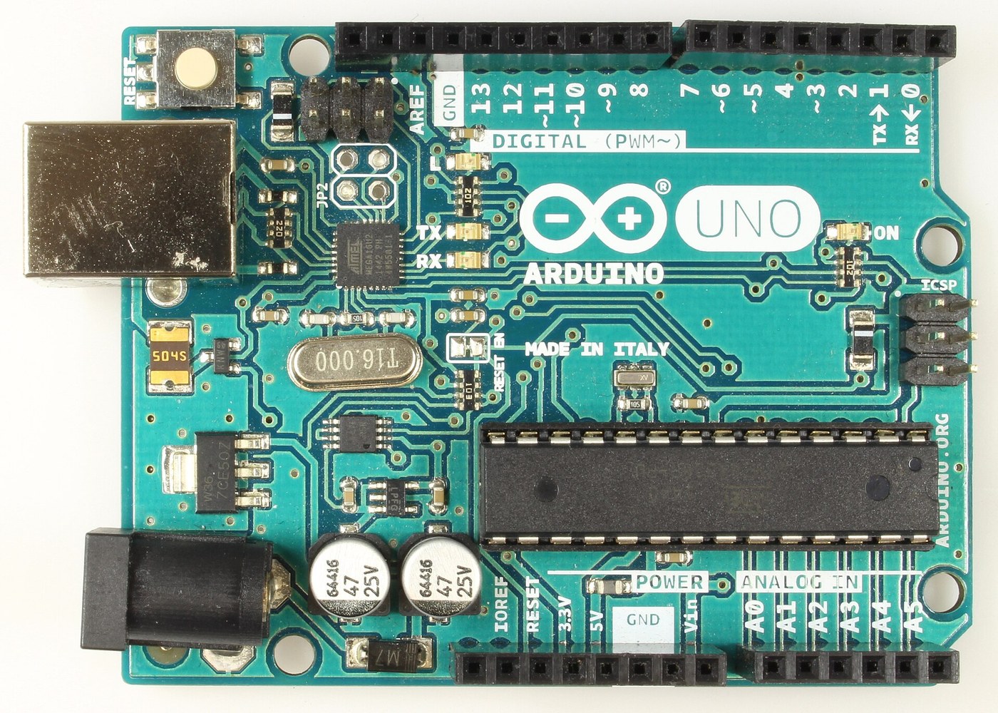


Arduino Uno R3: Assembled from Arduino's Open UNO-TH Rev3e Design Files and Flashed over ICSP
The Arduino Uno R3 is open hardware: Arduino publishes its schematic and board layout. This blueprint builds one from those files, part by part, then loads the firmware into its two processors.
Result: an Arduino Uno R3. An ATmega328P (16 MHz, 32 kB flash, 2 kB SRAM, 1 kB EEPROM) runs your programs; an ATmega16U2 turns USB into its serial link. It runs from USB (5.5 V at most) or 6-20 V at the DC jack.
Source: Arduino UNO-TH_Rev3e design files and the A000066 schematic and datasheet (Arduino, CC BY-SA). Unknown: how every bought part is made; no public source in hand says. The soldering method is ours. Picture: Wikimedia Commons.
ขั้นสูง
1 day
คำแนะนำ
1
1
Get the bare board
Get the bare board
Have the two-layer board made to Arduino's UNO-TH_Rev3e board layout (the .brd file of the design files). Check it against the schematic before fitting anything.
วัสดุสำหรับขั้นตอนนี้:
 แผ่นวงจรพิมพ์1 UNO-TH Rev3e layout
เครื่องมือที่ต้องใช้:
 กล้องส่องขยาย
2
2
Fit the small surface-mount parts
Fit the small surface-mount parts
Solder the chip parts to their marked places: resistor arrays RN1 (10K), RN2 and RN4 (1K), RN3 (22R); R1, R2 (1M); capacitors C1, C2, C4-C7, C10 (100n), C3, C8 (1u), C9, C11 (22p); varistors Z1, Z2; ferrite bead L1; inductor L2 (10 uH); diodes D2, D3; LEDs ON (green), L, RX, TX (yellow). Ours: flux, tweezers and hot air or a fine iron, checked under a loupe.
วัสดุสำหรับขั้นตอนนี้:
 ตัวต้านทานแบบชิปหลายตัวในตัวถังเดียว4 RN1-RN4
 ตัวต้านทานแบบชิป2 1M
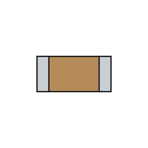 ตัวเก็บประจุเซรามิกแบบชิป11 7x100n, 2x1u, 2x22p
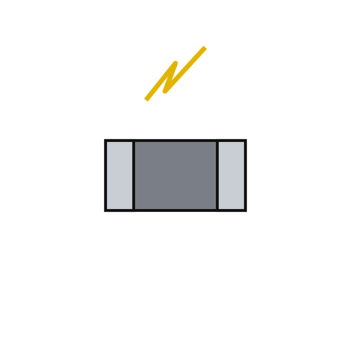 วาริสเตอร์แบบชิป2 Z1, Z2
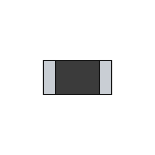 เม็ดเฟอร์ไรต์1 L1
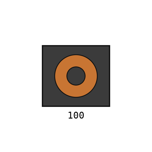 ตัวเหนี่ยวนำแบบติดผิว1 L2
 ไดโอดแบบติดผิว2 D2, D3
 LED แบบชิป4 1 green, 3 yellow
 ลวดตะกั่วบัดกรี1 a little
เครื่องมือที่ต้องใช้:
 ฟลักซ์
 แหนบปลายแหลม
 สถานีซ่อมด้วยลมร้อน
 หัวแร้งบัดกรีกล้องส่องขยาย
3
3
Fit the power and chip parts
Fit the power and chip parts
Solder the ATmega16U2 (U3), the 16 MHz resonator Y2 and crystal Y1, the 5 V regulator NCP1117 (U1) and 3.3 V regulator LP2985 (U2), the LMV358 op-amp (U5), the FDN340P transistor (T1), the M7 diode (D1), the 500 mA resettable fuse (F1) and the 47 uF capacitors PC1, PC2 with their polarity as marked.
วัสดุสำหรับขั้นตอนนี้:
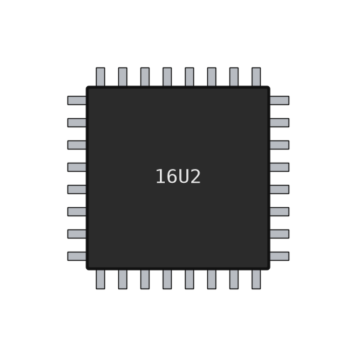 ไมโครคอนโทรลเลอร์ ATmega16U21 U3
 เรโซเนเตอร์เซรามิกเพียโซ1 Y2
 ผลึกควอตซ์1 Y1
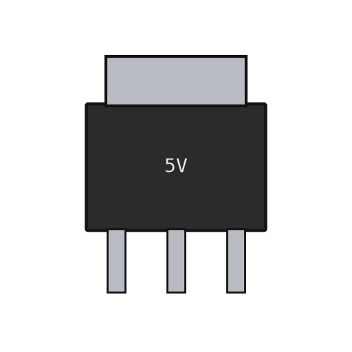 ตัวควบคุมแรงดันแบบเชิงเส้น2 U1 5 V, U2 3.3 V
 ไอซีออปแอมป์1 U5 LMV358
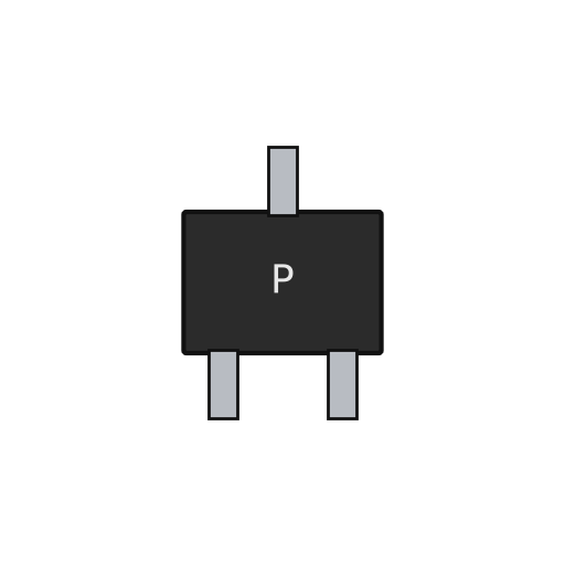 มอสเฟตชนิด P1 T1ไดโอดแบบติดผิว1 D1 M7
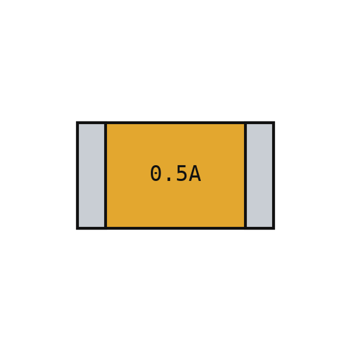 ฟิวส์รีเซ็ตได้1 F1
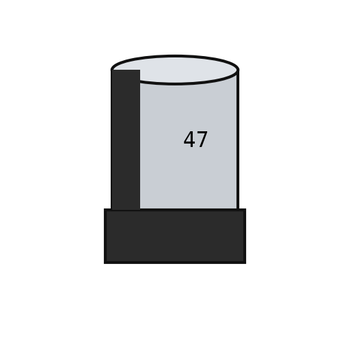 ตัวเก็บประจุแบบชิปมีขั้ว2 PC1, PC2ลวดตะกั่วบัดกรี1 a little
เครื่องมือที่ต้องใช้:
ฟลักซ์แหนบปลายแหลมสถานีซ่อมด้วยลมร้อนหัวแร้งบัดกรีกล้องส่องขยาย4
4
Fit the through-hole parts
Fit the through-hole parts
Solder the USB-B socket (X2), the DC jack (X1), the reset switch, the female headers (one 10-way, two 8-way, one 6-way) and the two 2x3 ICSP headers. Seat the ATmega328P in its place (ZU4).
วัสดุสำหรับขั้นตอนนี้:
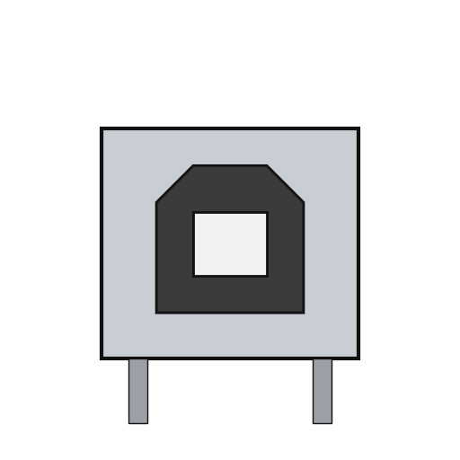 ซ็อกเก็ต USB-B1 X2
 แจ็กไฟแบบกระบอก1 X1
 ปุ่มกด1 RESET
 พินเฮดเดอร์6 10x1, 2x 8x1, 6x1 female; 2x 3x2 ICSP
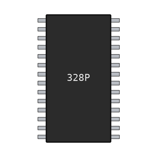 ไมโครคอนโทรลเลอร์ ATmega328P1 ZU4ลวดตะกั่วบัดกรี1 as needed
เครื่องมือที่ต้องใช้:
หัวแร้งบัดกรี5
5
Flash and check
Flash and check
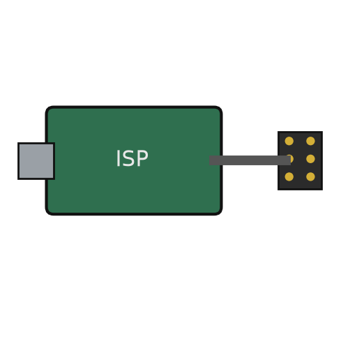
Check with a meter that 5 V and GND are not shorted. Through the ICSP headers, load the USB-to-serial firmware into the ATmega16U2 and the bootloader into the ATmega328P. Plug in USB: the green ON LED lights, and the blink test in the next step flashes the L LED. Ours: an AVR ISP programmer and a multimeter.
วัสดุสำหรับขั้นตอนนี้:
 เฟิร์มแวร์ Arduino Uno1 download
เครื่องมือที่ต้องใช้:
 มัลติมิเตอร์
 เครื่องโปรแกรม AVR ISP
 สาย USB-B
6
6
The blink test
The blink test
blink_test.ino: the same check as Arduino's Blink example. Upload it over USB from the Arduino IDE with the board set to Arduino Uno; the L LED on pin 13 turns on for one second and off for one second, over and over. If it does, both processors, the USB link and the bootloader work.
blink_test.inocpp
เครื่องมือที่ต้องใช้:
สาย USB-Bวัสดุ
24- 1 UNO-TH Rev3e layoutตัวยึดตำแหน่ง
- 4 RN1-RN4ตัวยึดตำแหน่ง
- 2 1Mตัวยึดตำแหน่ง
- 11 7x100n, 2x1u, 2x22pตัวยึดตำแหน่ง
- 2 Z1, Z2ตัวยึดตำแหน่ง
- 1 L1ตัวยึดตำแหน่ง
- ตัวยึดตำแหน่ง
- 1 D1 M7ตัวยึดตำแหน่ง
- 4 1 green, 3 yellowตัวยึดตำแหน่ง
- 1 as neededตัวยึดตำแหน่ง
- ตัวยึดตำแหน่ง
- ตัวยึดตำแหน่ง
- 1 Y1ตัวยึดตำแหน่ง
- 2 U1 5 V, U2 3.3 Vตัวยึดตำแหน่ง
- 1 U5 LMV358ตัวยึดตำแหน่ง
- 1 T1ตัวยึดตำแหน่ง
- 1 F1ตัวยึดตำแหน่ง
- 2 PC1, PC2ตัวยึดตำแหน่ง
- 1 X2ตัวยึดตำแหน่ง
- ตัวยึดตำแหน่ง
- ตัวยึดตำแหน่ง
- ตัวยึดตำแหน่ง
- ตัวยึดตำแหน่ง
- 1 downloadตัวยึดตำแหน่ง
เครื่องมือที่จำเป็น
8- ตัวยึดตำแหน่ง
- ตัวยึดตำแหน่ง
- ตัวยึดตำแหน่ง
- ตัวยึดตำแหน่ง
- 2 vendors sell this, none ship to you yetตัวยึดตำแหน่ง
- ตัวยึดตำแหน่ง
- ตัวยึดตำแหน่ง
- 1 vendor sell this, none ship to you yetตัวยึดตำแหน่ง
พิมพ์เขียวนี้สร้าง
บลูพริ้นท์ที่เกี่ยวข้อง
บลูพริ้นท์เหล่านี้แบ่งปันความรู้ — เทคนิค วัสดุ หรือหลักการ
CC0 สาธารณสมบัติ
พิมพ์เขียวนี้เผยแพร่ภายใต้ CC0 คุณสามารถคัดลอก แก้ไข แจกจ่าย และใช้งานผลงานนี้เพื่อวัตถุประสงค์ใดก็ได้ โดยไม่ต้องขออนุญาต
สนับสนุนเมกเกอร์โดยซื้อสินค้าผ่านพิมพ์เขียวของพวกเขา ซึ่งพวกเขาจะได้รับ ค่าคอมมิชชันเมกเกอร์ ที่ผู้ขายกำหนด หรือสร้างเวอร์ชันใหม่ของพิมพ์เขียวนี้และรวมเป็นการเชื่อมต่อในพิมพ์เขียวของคุณเพื่อแบ่งรายได้