ศิลปะ
ความงามและสุขภาพ
งานฝีมือ
วัฒนธรรมและประวัติศาสตร์
ความบันเทิง
สิ่งแวดล้อม
อาหารและเครื่องดื่ม
วิศวกรรมย้อนรอย
วิทยาศาสตร์
กีฬา
เทคโนโลยี
อุปกรณ์สวมใส่


Commutating Without Brushes: Hall Elements Instead of Carbon
Every tool in this batch so far has had a brushed motor in it, and a brushed motor spends part of its energy grinding carbon into dust and throwing sparks where the current reverses.
The commutator is not there to make torque. It is there to *time* the current, so the stator's field stays roughly square to the rotor's. Once you can sense where the rotor is by some other means, the brushes are an expensive mechanical solution to an electrical problem.
Manteuffel and Kovatch at General Electric filed the answer in 1962: **Hall elements** reading the rotor's own magnetic field, gating solid-state switches that energise the stator windings in sequence. This rung builds that idea up from one sensor and one coil, then runs a real motor and reads its commutation on the oscilloscope.
ขั้นสูง
About 5 hours
คำแนะนำ
1
1
Read the claim, and name what the brush was doing
Read the claim, and name what the brush was doing
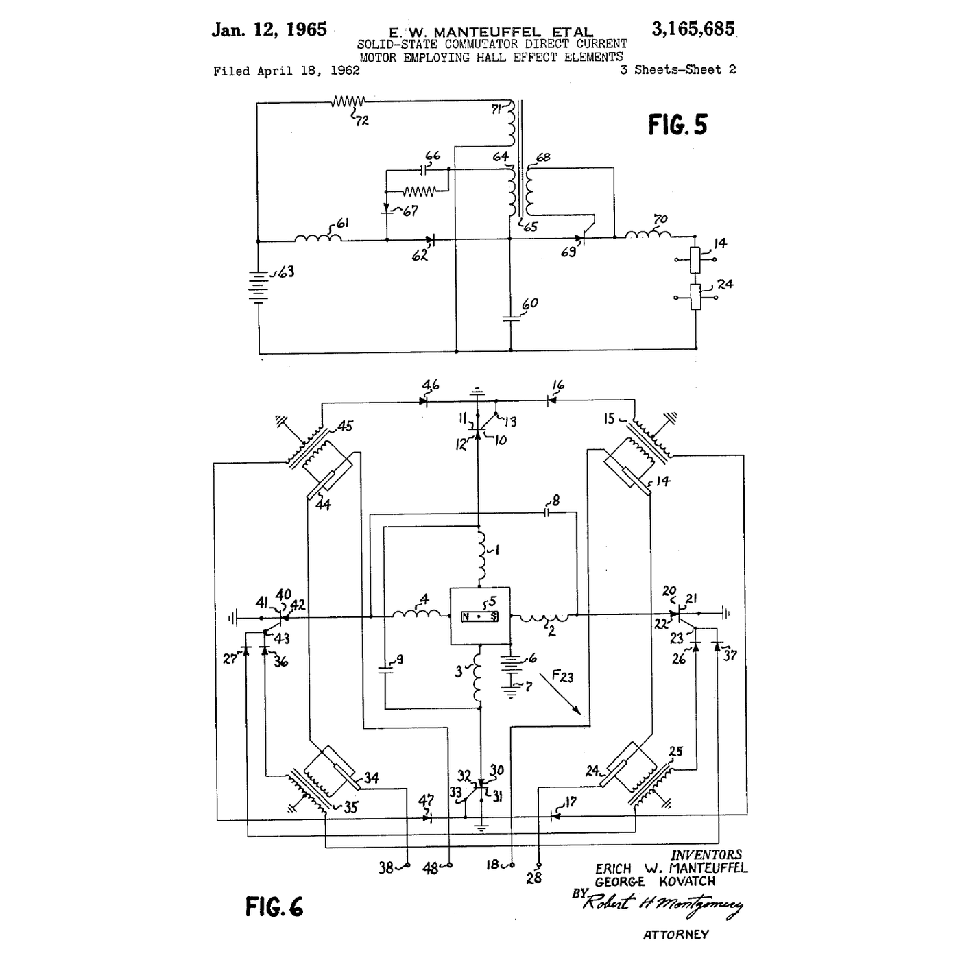
**US 3,165,685**, *Solid-state commutator direct current motor employing Hall effect elements*, Erich W. Manteuffel and George Kovatch, General Electric; filed **18 April 1962**, granted **12 January 1965**, long expired. The figure on this page is its own sheet 2 — FIG. 5 is the Hall element and its amplifier, FIG. 6 the whole machine with four Hall generators around the rotor feeding controlled rectifiers.
The key sentence describes Hall generators producing *output signals dependent upon both the polarity of the energizing current and the polarity of the magnetic flux*. That double dependence is why a Hall element and not a coil: a Hall element gives you **which way** the field points, standing still, with no motion required. A search coil only tells you the field is changing.
The patent's own machine has **four** windings rather than three phases, and it says what that costs in so many words: *"the value of θ changes from 135° at a time when a new winding begins conducting unidirectional current to 45° at a time immediately before a subsequent winding begins conducting"*. A 90° sweep either side of the useful angle. Step 5 puts that against the 60° sweep of the three-phase motors that replaced it.
That distinction is the whole reason this works at zero speed. Every brushless motor can also be commutated from its own **back-EMF**, which is cheaper and needs no sensors — but back-EMF is zero when the rotor is not turning, so a sensorless motor has to be started blind. A tool that must produce full torque from rest cannot do that, which is why tool motors carry Hall sensors and drone motors mostly do not.
Write down the three parts of the arrangement before you build anything: a **rotor magnet**, **sensors that read its angle**, and **switches those sensors gate**. Everything after this is those three.
2
2
Make one Hall element tell you which pole is facing it
Make one Hall element tell you which pole is facing it
Put a linear Hall sensor from the pack on the breadboard: supply, ground, output. Power it from 5 V and put the meter on the output. With no magnet near, it should sit at about half the supply — that is the zero-field point.
Bring one face of a neodymium magnet up to it and read the output. Turn the magnet over and read again. One pole pushes the output up from the mid-point, the other pushes it down. **That is the patent's sentence, on your bench**: the output depends on the polarity of the flux, not just its strength.
Now measure the shape. Mount the magnet on something you can rotate — a pencil through a cardboard disc is enough — and record the output every 15° through a full turn. Plot it. You get something close to a sine wave, and its two zero-crossings are exactly the positions a switch should change state at.
Do the same with a digital (latching) Hall sensor if your pack has one. Its output does not vary; it snaps between the rails, with hysteresis so it does not chatter at the crossing. That is the part a real motor uses, because a switch wants a decision and not a measurement.
Keep the magnets away from the meter, the scope, any card with a magnetic stripe and each other. Neodymium magnets of any size snap together hard enough to shatter and to catch skin between them.
เครื่องมือที่ต้องใช้:
 เบรดบอร์ด
 ชุดสาย Dupont (ผู้-เมีย)
 ชุดเซนเซอร์ฮอลล์เอฟเฟกต์
 ชุดแม่เหล็กนีโอดิเมียม
 มัลติมิเตอร์ดิจิทัล — เลือกย่านอัตโนมัติ ค่า RMS แท้
 ออสซิลโลสโคปดิจิทัล
 แหล่งจ่ายไฟตั้งโต๊ะ
 แว่นตานิรภัยใส
3
3
Let the sensor switch a coil
Let the sensor switch a coil
One sensor, one switch, one coil: the smallest complete version of the idea.
Wind about a hundred turns of enamelled copper wire into a flat coil 25–30 mm across and scrape the enamel off both ends — enamel is insulation and a coil that reads open-circuit on the meter almost always just has enamel under the clip. Check it reads a few ohms.
Wire the coil from the supply to the **drain** of the logic-level MOSFET, source to ground, and the digital Hall sensor's output to the gate. Put a **flyback diode** across the coil, cathode to the positive end. This is not optional: switching off an inductor produces a voltage spike that will destroy the MOSFET, and the diode gives the collapsing current somewhere to go.
Fix the coil down, mount the magnet on a shaft that can spin freely above it, and place the Hall sensor where it sees the magnet slightly *before* the coil does. Spin it by hand. The coil should pulse once per revolution, in the same place every time, and give the magnet a push.
Put the scope on the gate and on the drain. You are looking at commutation: a gate signal that follows rotor angle, and a drain that snaps down when the coil conducts and rings when it stops. Move the sensor a few degrees around the axis and watch the pulse move with it. **That is commutation timing**, and step 5 works out how much it matters.
One coil cannot start itself from every position and cannot run smoothly — a real motor uses three phases and six switches for exactly that reason. What it can do is show you the whole idea in parts you can see.
วัสดุสำหรับขั้นตอนนี้:
 ลวดทองแดงอาบน้ำยา 22 AWG1 ชิ้น
 สายไฟต่อวงจร1 ชิ้น
เครื่องมือที่ต้องใช้:
เบรดบอร์ดชุดสาย Dupont (ผู้-เมีย)ชุดเซนเซอร์ฮอลล์เอฟเฟกต์ MOSFET ระดับลอจิก IRLZ44Nชุดแม่เหล็กนีโอดิเมียมออสซิลโลสโคปดิจิทัลมัลติมิเตอร์ดิจิทัล — เลือกย่านอัตโนมัติ ค่า RMS แท้แหล่งจ่ายไฟตั้งโต๊ะ
 สถานีบัดกรีพร้อมหัวแร้ง
 ลวดบัดกรี 63/37 แกนยางสน
 คีมปอกสายไฟแว่นตานิรภัยใส
4
4
Run a real one and read its commutation
Run a real one and read its commutation
Now the production version. Connect the brushless motor to the speed controller and the controller to the bench supply with the current limit set low — an amp to start with. Bolt the motor down. An unsecured brushless motor with anything attached to its shaft is genuinely dangerous.
Two things to look at with the scope.
**The drive waveforms.** Put one probe on each of two motor phases, referenced to the supply negative. You will see the six-step pattern: each phase driven high, then driven low, then left floating for a third of the cycle, in rotation. Count the steps per revolution and divide by six to get the number of pole pairs — this is how you find out what a motor is without a datasheet.
**The back-EMF.** During the floating third, that phase is disconnected and the winding is generating. Look at the trapezoidal voltage there. Then unplug the controller entirely and spin the motor by hand while watching the same two phases: clean three-phase generation, no electronics involved. A brushless motor is an alternator you are driving backwards, and that is not a metaphor.
Increase the supply current limit slowly and watch the commutation frequency rise with speed. Put the infrared thermometer on the windings; a brushless motor runs the heat in the **stator**, on the outside where it can escape, while a brushed motor makes much of its heat in the rotor where it cannot. That single difference is most of why a brushless tool can be smaller for the same output.
No propeller, no wheel, no loose collet. Nothing on the shaft that can come off.
เครื่องมือที่ต้องใช้:
 มอเตอร์ไร้แปรงถ่าน
 ตัวควบคุมความเร็วอิเล็กทรอนิกส์แหล่งจ่ายไฟตั้งโต๊ะออสซิลโลสโคปดิจิทัลมัลติมิเตอร์ดิจิทัล — เลือกย่านอัตโนมัติ ค่า RMS แท้
 แคลมป์มิเตอร์ AC/DC 600 แอมป์
 เทอร์โมมิเตอร์อินฟราเรด
 เครื่องวิเคราะห์ลอจิก
 กระบังหน้าแว่นตานิรภัยใส
5
5
Why the angle matters, and how much
Why the angle matters, and how much
กำลังโหลดสมุด Jupyter…
6
6
History and context
History and context
**Attribution.** US 3,165,685, *Solid-state commutator direct current motor employing Hall effect elements*, Erich W. Manteuffel and George Kovatch, assigned to General Electric; filed 18 April 1962, granted 12 January 1965, expired. The drawing on this page is the patent's own sheet 2.
**Why 1962 and not 1879.** Edwin Hall discovered the effect in 1879 and it stayed a laboratory curiosity for seventy years, because the voltage it produces in a metal is microvolts. Semiconductors changed that: the Hall voltage in a doped semiconductor is thousands of times larger, and by the late 1950s indium antimonide and germanium elements were practical. The patent needed two things that arrived at almost the same time — a usable Hall element and a switch that could carry motor current, which in 1962 was a **controlled rectifier**, the thyristor.
**Why it took another thirty years to reach your drill.** A brushless motor is a motor plus a power electronics problem. Until cheap power MOSFETs and a microcontroller to drive them existed, the electronics cost more than the motor saved, and cordless tools stayed brushed. The first brushless cordless tools arrive in the 2000s, on the back of the MOSFET rung and the lithium pack of this batch — the motor, the cells and the switches all had to be ready at once.
**Honest limits.** A brushless motor cannot run on DC alone; it is useless without its controller, and when the controller dies the motor is a paperweight. It is harder to repair, harder to diagnose and it fails in ways that need a scope rather than a look. Six-step commutation is audibly rougher than sinusoidal drive, which is why cheap brushless motors whine. And the torque advantage is not the motor being better at making force — it is that the heat comes out somewhere useful, so the same frame can be pushed harder.
วัสดุ
2- 1 ชิ้นตัวยึดตำแหน่ง
- 1 ชิ้นตัวยึดตำแหน่ง
เครื่องมือที่จำเป็น
18- ตัวยึดตำแหน่ง
- ชุดเซนเซอร์ฮอลล์เอฟเฟกต์ค่าคอมมิชชัน 10%ตัวยึดตำแหน่ง
- ตัวยึดตำแหน่ง
- ตัวยึดตำแหน่ง
- ออสซิลโลสโคปดิจิทัลค่าคอมมิชชัน 10%Magento Legacy Storeships internationallyตัวยึดตำแหน่ง
- ตัวยึดตำแหน่ง
- ตัวยึดตำแหน่ง
- ตัวยึดตำแหน่ง
- สถานีบัดกรีพร้อมหัวแร้งค่าคอมมิชชัน 10%ตัวยึดตำแหน่ง
- ตัวยึดตำแหน่ง
- ตัวยึดตำแหน่ง
- ตัวยึดตำแหน่ง
- ตัวควบคุมความเร็วอิเล็กทรอนิกส์ค่าคอมมิชชัน 10%Magento Legacy Storeships internationallyตัวยึดตำแหน่ง
- ตัวยึดตำแหน่ง
- ตัวยึดตำแหน่ง
- เครื่องวิเคราะห์ลอจิกค่าคอมมิชชัน 10%ตัวยึดตำแหน่ง
- ตัวยึดตำแหน่ง
บลูพริ้นท์ที่เกี่ยวข้อง
บลูพริ้นท์เหล่านี้แบ่งปันความรู้ — เทคนิค วัสดุ หรือหลักการ
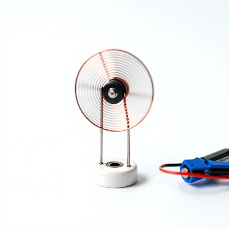


CC0 สาธารณสมบัติ
พิมพ์เขียวนี้เผยแพร่ภายใต้ CC0 คุณสามารถคัดลอก แก้ไข แจกจ่าย และใช้งานผลงานนี้เพื่อวัตถุประสงค์ใดก็ได้ โดยไม่ต้องขออนุญาต
สนับสนุนเมกเกอร์โดยซื้อสินค้าผ่านพิมพ์เขียวของพวกเขา ซึ่งพวกเขาจะได้รับ ค่าคอมมิชชันเมกเกอร์ ที่ผู้ขายกำหนด หรือสร้างเวอร์ชันใหม่ของพิมพ์เขียวนี้และรวมเป็นการเชื่อมต่อในพิมพ์เขียวของคุณเพื่อแบ่งรายได้