การทำงานร่วมกัน
ศิลปะ
ความงามและสุขภาพ
งานฝีมือ
วัฒนธรรมและประวัติศาสตร์
ความบันเทิง
สิ่งแวดล้อม
อาหารและเครื่องดื่ม
วิศวกรรมย้อนรอย
วิทยาศาสตร์
กีฬา
เทคโนโลยี
อุปกรณ์สวมใส่

Pocket Morse Code Learning Board - v.2
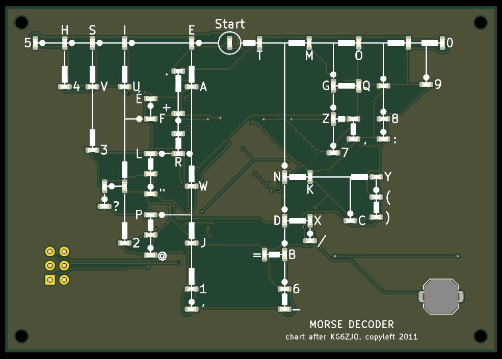
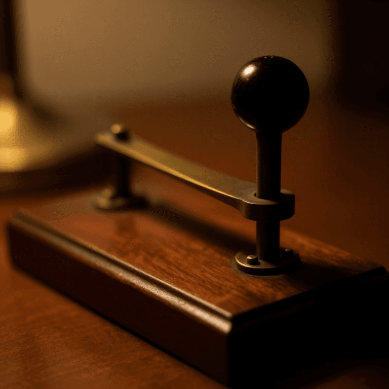
The complete pocket Morse decoder, 88 x 62 mm: every letter, the figures 0-9, the thirteen punctuation signs of the international code and the accented E, each with its own LED on Dave Nathanson's decoding chart. Press the key short for a dot and long for a dash, and the LED of the character you have reached lights; pause, and it blinks.
It runs on one CR2032 coin cell and sleeps between uses. The board was drawn with Youblob's Draw PCB, and its checks pass, but it has not been built yet.
ขั้นสูง
About 1 day, plus board delivery
คำแนะนำ
1
1
LED current and keying speed
LED current and keying speed
กำลังโหลดสมุด Jupyter…
2
2
The letters-only board, before it
The letters-only board, before it
The same design with 27 LEDs. This one adds the figures and the signs, 59 LEDs in all.
3
3
Read the chart
Read the chart
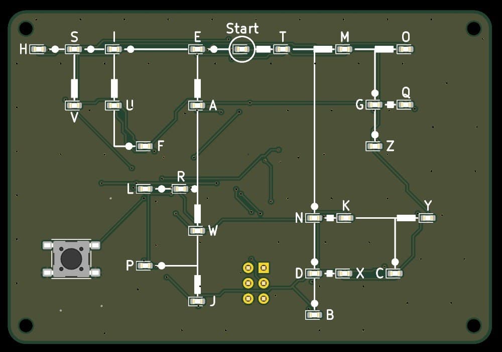
Dave Nathanson's (KG6ZJO) complete chart adds the figures to his letters: "A-Z and Numbers (I left off the punctuation & symbols for simplicity)". This board adds them back from ITU-R M.1677-1 on new branches: . , : ? ' - / ( ) " = + @ and the accented E. Eight unlabelled LEDs are waypoints on the way to a figure or sign.
4
4
The schematic
The schematic
ATmega328P on its internal 8 MHz clock, straight from the coin cell; 59 LEDs charlieplexed on nine lines (PC0-PC5, PD0, PD1, PD3) through 300 Ω resistors; the key on INT0; a 2x3 ISP footprint.
กำลังโหลด KiCanvas viewer...
ตัวดูแบบ PCB ระดับมืออาชีพ
5
5
The board
The board
Two layers, 88 x 62 mm. The chart, LEDs and key on the front; the chip, resistors, capacitors and cell holder on the back.
กำลังโหลด KiCanvas viewer...
ตัวดูแบบ PCB ระดับมืออาชีพ
6
6
Order the board
Order the board
Open the board in KiCad and plot Gerber and drill files (File > Fabrication Outputs). Order a two-layer board, 1.6 mm thick, from any board maker that takes Gerbers.
วัสดุสำหรับขั้นตอนนี้:
 แผ่นวงจรพิมพ์1 ชิ้น
เครื่องมือที่ต้องใช้:
 คอมพิวเตอร์ที่ติดตั้ง Arduino IDE
7
7
Solder the parts
Solder the parts
Back first: paste and reflow U1, R1-R10, C1-C3 and the cell holder BT1 with hot air. Then the front: the 59 red LEDs D1-D59 with pad 1 (cathode) as the board's assembly drawing shows, and the key SW1, a two-pad 6 x 6 mm switch to match its footprint. J1 is optional. Clean off the flux, then test each LED's direction with the meter's diode test.
วัสดุสำหรับขั้นตอนนี้:
 ไมโครคอนโทรลเลอร์ ATmega328P1 ชิ้น
 LED แบบชิป59 ชิ้น
 ตัวต้านทานแบบชิป10 ชิ้น
 ตัวเก็บประจุเซรามิกแบบชิป3 ชิ้น
 ปุ่มกด1 ชิ้น
 รังถ่าน1 ชิ้น
 ครีมบัดกรี (ไร้ตะกั่ว)1 ชิ้น
 ลวดตะกั่วบัดกรี1 ชิ้น
เครื่องมือที่ต้องใช้:
 สถานีซ่อมด้วยลมร้อน
 หัวแร้งบัดกรี
 แหนบปลายแหลม
 ฟลักซ์
 แว่นขยาย
 มัลติมิเตอร์
 ไอโซโพรพิลแอลกอฮอล์ 99 %
8
8
The firmware
The firmware
pocket_morse_decoder_complete.ino: every timing is a named constant at the top of the sketch. Board in the Arduino IDE: Arduino Pro or Pro Mini, ATmega328P (3.3V, 8 MHz).
pocket_morse_decoder_complete.inoarduino
9
9
Set the fuses and upload
Set the fuses and upload
Do not use Burn Bootloader: the Pro board setting expects a crystal, and this board has none. Hold an ISP programmer's 2x3 pins on J1 and set the internal 8 MHz clock: avrdude -c usbasp -p m328p -U lfuse:w:0xE2:m -U hfuse:w:0xD9:m -U efuse:w:0xFF:m. Then, in the Arduino IDE, use Sketch > Upload Using Programmer.
เครื่องมือที่ต้องใช้:
 เครื่องโปรแกรม AVR ISPคอมพิวเตอร์ที่ติดตั้ง Arduino IDE
10
10
Print the back shell
Print the back shell
An open-front tray, 92.6 x 66.6 x 8.3 mm, with four standoffs for M2 screws, a notch and floor opening to slide the cell out and an opening under J1. PLA, 0.2 mm layers, 20 % infill, printed on its floor.
11
11
Fit the shell
Fit the shell
The standoffs hold the board 6.7 mm above the floor: measure your cell holder with a cell in it before you print. Check the holder's open end faces the board's bottom edge, where the shell's cell notch is. Slide in a CR2032 and screw the board into the shell with four M2 x 8 self-tapping screws.
วัสดุสำหรับขั้นตอนนี้:
 เส้นใย PLA1 ชิ้น
 สกรูเกลียวปล่อย4 ชิ้น
 ถ่านกระดุม CR20321 ชิ้น
เครื่องมือที่ต้องใช้:
 เครื่องพิมพ์สามมิติแบบเส้นใย (FDM)
 เวอร์เนียคาลิเปอร์
 ชุดไขควงความละเอียดสูง
12
12
Troubleshooting
Troubleshooting
Pocket Morse decoder troubleshooting.
Flow
Loading...
13
13
History and honest limits
History and honest limits
The letters and figures follow **Dave Nathanson**'s (KG6ZJO) complete chart of 2011, shared as copyleft. Where the signs sit is ours; their codes are ITU-R M.1677-1's. The board, sizes, parts and timings are ours, drawn with Youblob's Draw PCB: its ERC and DRC pass with no errors and every LED's wiring, code and label was checked against the firmware by script, but it has not been built, flashed or tested.
วัสดุ
12- 1 ชิ้นตัวยึดตำแหน่ง
- ตัวยึดตำแหน่ง
- 59 ชิ้นตัวยึดตำแหน่ง
- 10 ชิ้นตัวยึดตำแหน่ง
- ตัวยึดตำแหน่ง
- ตัวยึดตำแหน่ง
- ตัวยึดตำแหน่ง
- 1 ชิ้นตัวยึดตำแหน่ง
- 1 ชิ้นตัวยึดตำแหน่ง
- 1 ชิ้นตัวยึดตำแหน่ง
- 4 ชิ้นตัวยึดตำแหน่ง
- 1 ชิ้นตัวยึดตำแหน่ง
เครื่องมือที่จำเป็น
12- ตัวยึดตำแหน่ง
- ตัวยึดตำแหน่ง
- 2 vendors sell this, none ship to you yetตัวยึดตำแหน่ง
- ตัวยึดตำแหน่ง
- ตัวยึดตำแหน่ง
- ตัวยึดตำแหน่ง
- ตัวยึดตำแหน่ง
- ตัวยึดตำแหน่ง
- ตัวยึดตำแหน่ง
- ตัวยึดตำแหน่ง
- ตัวยึดตำแหน่ง
- ตัวยึดตำแหน่ง
ไฟล์ออกแบบ
1พิมพ์เขียวนี้สร้าง

บลูพริ้นท์ที่เกี่ยวข้อง
บลูพริ้นท์เหล่านี้แบ่งปันความรู้ — เทคนิค วัสดุ หรือหลักการ

CC0 สาธารณสมบัติ
พิมพ์เขียวนี้เผยแพร่ภายใต้ CC0 คุณสามารถคัดลอก แก้ไข แจกจ่าย และใช้งานผลงานนี้เพื่อวัตถุประสงค์ใดก็ได้ โดยไม่ต้องขออนุญาต
สนับสนุนเมกเกอร์โดยซื้อสินค้าผ่านพิมพ์เขียวของพวกเขา ซึ่งพวกเขาจะได้รับ ค่าคอมมิชชันเมกเกอร์ ที่ผู้ขายกำหนด หรือสร้างเวอร์ชันใหม่ของพิมพ์เขียวนี้และรวมเป็นการเชื่อมต่อในพิมพ์เขียวของคุณเพื่อแบ่งรายได้