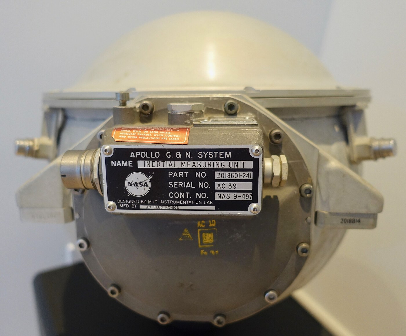


The Inertial Guidance Platform
Talimatlar
Show that a spinning rotor holds its direction
Show that a spinning rotor holds its direction
Rigidity in space is the property everything else rests on.
- Mount a heavy rotor in a two-axis gimbal so it is free to point in any direction.
- Spin it up and note the direction its axis points.
- Carry the whole assembly around the room, rotating the frame in every direction.
- Watch the spin axis.
The frame turns; the spin axis does not. The rotor is holding an orientation fixed relative to space itself while its mounting rotates around it, and the gimbals are simply allowing that to happen without transmitting torque.
Now push gently on the spinning rotor and observe: it does not move in the direction you pushed, but at right angles to it. That is precession, and it is the source of every counter-intuitive behaviour in the rest of this blueprint.
See the Sperry gyrocompass blueprint for how the same property was used to find true north at sea. The difference in application is instructive: the gyrocompass deliberately CONSTRAINS the gyro so Earth’s rotation forces it to seek north, while a guidance platform tries to leave it entirely unconstrained.Bu adım için malzemeler:
 Bilyalı Rulman4 adet
 Pirinç Yuvarlak Çubuk1 adet
 Alüminyum Plaka1 adet
Gerekli aletler:
 Metal Torna Tezgâhı
 4 İnç Freze Mengenesi
 Komparatör Saati
 Dijital Kumpas 6 İnç
 Dijital Takometre
 Dijital Açı Ölçer
 Şeffaf Koruyucu Gözlük
Build a stable platform on three gimbals
Build a stable platform on three gimbals
Isolate a small platform from every rotation of the vehicle around it.
- Build three nested gimbal rings, each free about a different axis.
- Mount the inner platform carrying the gyros and accelerometers.
- Fit pickoffs to sense any relative rotation, and small torque motors to drive each gimbal.
- Close a loop that drives the motors to keep the pickoffs reading zero.
The platform now stays fixed in inertial space while the vehicle rotates freely around it, and the gimbal angles read out the vehicle’s attitude directly. The loop is not steering the platform — it is removing friction, driving the gimbals so the platform never has to be pushed.
Three gimbals have a famous flaw. Rotate the vehicle so two gimbal axes line up and the platform loses a degree of freedom entirely — gimbal lock, after which the platform tumbles and the reference is destroyed. Apollo carried a display warning the crew away from those attitudes, and Michael Collins famously suggested they carry a fourth gimbal instead.
The fix is a redundant fourth gimbal, or abandoning the mechanical platform altogether for a strapdown system where sensors are bolted to the airframe and the transformation is done in software. Cheap computing killed the gimballed platform — the mathematics was always possible, the processing was not.Bu adım için malzemeler:
Alüminyum Plaka2 adetBilyalı Rulman6 adet Çelik pim6 adet
 M5 silindir başlı vidalar12 adet
Gerekli aletler:
4 İnç Freze MengenesiMetal Torna Tezgâhı Sütunlu MatkapKomparatör SaatiDijital Kumpas 6 İnçDijital Açı Ölçer
 Tork AnahtarıŞeffaf Koruyucu Gözlük
The drift logger sketch
The drift logger sketch
Upload this, leave the sensor completely still, and let it run for ten minutes.
It first averages 2000 stationary samples to measure bias — whatever a still sensor reads IS bias plus gravity, and gravity is known, so the average removes both. Then it integrates the remaining signal twice and prints apparent velocity and apparent position once per second.
Paste the output into a spreadsheet and plot position against time. A sensor that never moved will report metres, then tens of metres, growing with the SQUARE of elapsed time.
Bu adım için malzemeler:
 Eylemsizlik ölçüm birimi (6 eksen)1 adet
 Mikrodenetleyici kartı1 adet
 Bağlantı teli1 reel
Gerekli aletler:
 Arduino IDE Kurulu Bilgisayar
 Laboratuvar Sınıfı Dijital Multimetre
 Osiloskop
Measure accelerometer bias, and watch it become distance
Measure accelerometer bias, and watch it become distance
This is where the errors come from, and the mechanism is arithmetic rather than mechanical.
- Leave an accelerometer perfectly still and log its output for ten minutes.
- Compute the mean — this is bias, and it should be zero and will not be.
- Integrate the logged signal once to get apparent velocity, and again to get apparent position.
- Plot both against time.
A stationary sensor reports a steadily growing velocity and a position error that grows with the square of time. A bias of one milli-g — roughly a thousandth of gravity — produces about 176 metres of position error after ten minutes, from a sensor that never moved.
That is the central problem of inertial navigation and it cannot be solved by better integration. Integration is faithful; it is faithfully integrating an error.
Which is why inertial systems are always eventually corrected from outside — star trackers, radio updates, GPS today. Inertial guidance is unjammable and drifts; external references are jammable and do not. Modern systems fuse both, using each to cover the other’s weakness, and that combination is the standard answer wherever navigation must be trusted.Bu adım için malzemeler:
Eylemsizlik ölçüm birimi (6 eksen)1 adetMikrodenetleyici kartı1 adet Milimetrik Kağıt1 pad
Gerekli aletler:
OsiloskopLaboratuvar Sınıfı Dijital Multimetre Ayarlanabilir Tezgâh Güç Kaynağı
 Havya İstasyonuDijital Açı ÖlçerŞeffaf Koruyucu Gözlük
Separate gravity from acceleration, because the sensor cannot
Separate gravity from acceleration, because the sensor cannot
An accelerometer cannot tell you which way is up, and this is not a defect you can engineer away.
- Hold an accelerometer stationary and note it reads 1 g upward.
- Drop it — in free fall — and note it reads zero.
- Tilt it slowly and watch the components change.
- Now consider a sensor reading 1 g and try to determine whether it is sitting still or accelerating upward in space.
There is no measurement that distinguishes them. That is the equivalence principle, and it means the guidance computer must SUBTRACT a modelled gravity vector from every reading — which requires knowing where you are, which is what you were trying to compute.
The loop closes on itself: use current position estimate to look up gravity, subtract it, integrate to update position, repeat. Errors in position produce errors in the gravity model, which produce errors in position.
This is why serious inertial systems carry a detailed gravity model rather than a constant, and why Earth’s gravity field has been mapped by satellite to remarkable precision. It is also why a stationary system can be self-calibrated: anything it reads while parked is, by definition, bias plus gravity, and gravity is known.Bu adım için malzemeler:
Eylemsizlik ölçüm birimi (6 eksen)1 adetMilimetrik Kağıt1 padGerekli aletler:
Dijital Açı ÖlçerOsiloskopLaboratuvar Sınıfı Dijital Multimetre Ağır Çekim Video Çeken Akıllı TelefonŞeffaf Koruyucu Gözlük
Align the platform before launch, and know why it takes so long
Align the platform before launch, and know why it takes so long
An inertial system must be told where it is once. Everything after that is arithmetic.
- With the platform level and stationary, use the accelerometers to find the local vertical — gravity defines it.
- Now use the gyros to detect Earth’s rotation, about 15 degrees per hour, and find the direction of its axis.
- From vertical and the rotation axis, compute true north.
- Time how long the measurement takes to become repeatable.
Gyrocompassing finds north with no magnetic compass and no outside signal, using only the fact that the Earth turns — but the signal is tiny and it takes minutes of averaging to extract it. That is why a launch vehicle sits on the pad with its guidance running long before ignition, and why the countdown includes a point after which alignment cannot be repeated without starting over.
The magnetic compass, by contrast, is instant and points at a wandering magnetic pole that is not north. One is slow and true; the other is fast and approximately right — and which you want depends entirely on whether you are steering a ship or hitting a target 300 km away.
This closes the batch. The nozzle raised exhaust velocity, staging beat the logarithm, the gimbal kept the vehicle upright, and the platform knows which way that is. What remains is coming back down, which is the heat shield blueprint — and a different problem entirely, because on the way up you are spending energy and on the way down you must get rid of it.Bu adım için malzemeler:
Eylemsizlik ölçüm birimi (6 eksen)1 adetMilimetrik Kağıt1 padGerekli aletler:
Dijital Açı ÖlçerOsiloskopLaboratuvar Sınıfı Dijital MultimetreAyarlanabilir Tezgâh Güç KaynağıDijital TakometreŞeffaf Koruyucu GözlükMalzemeler
9- Yer Tutucu
- 1 adetYer Tutucu
- 3 adetYer Tutucu
- 6 adetYer Tutucu
- 12 adetYer Tutucu
- Yer Tutucu
- 1 adetYer Tutucu
- 1 reelYer Tutucu
- 1 padYer Tutucu
Gerekli Aletler
15- Yer Tutucu
- Yer Tutucu
- Yer Tutucu
- Yer Tutucu
- Yer Tutucu
- Yer Tutucu
- Yer Tutucu
- Yer Tutucu
- Yer Tutucu
- Yer Tutucu
- Yer Tutucu
- Yer Tutucu
- Yer Tutucu
- Yer Tutucu
- Yer Tutucu
İlgili Blueprint'ler
Bu blueprint'ler bilgi paylaşır — teknikler, malzemeler veya ilkeler


CC0 Kamu Malı
Bu plan CC0 lisansıyla yayınlanmıştır. İzin almadan kopyalayabilir, değiştirebilir, dağıtabilir ve herhangi bir amaçla kullanabilirsiniz.
Planı üzerinden ürün satın alarak Maker'ı destekleyin, böylece Maker Komisyonu Satıcılar tarafından belirlenen komisyonu kazanırlar veya bu Planın yeni bir versiyonunu oluşturun ve gelir paylaşımı için kendi Planınıza bağlantı olarak ekleyin.