SANAT
GÜZELLİK & SAĞLIK
ZANAAT
KÜLTÜR & TARİH
EĞLENCE
ÇEVRE
YİYECEK & İÇECEK
TERS MÜHENDİSLİK
BİLİMLER
SPOR
TEKNOLOJİ
GİYİLEBİLİR ÜRÜNLER
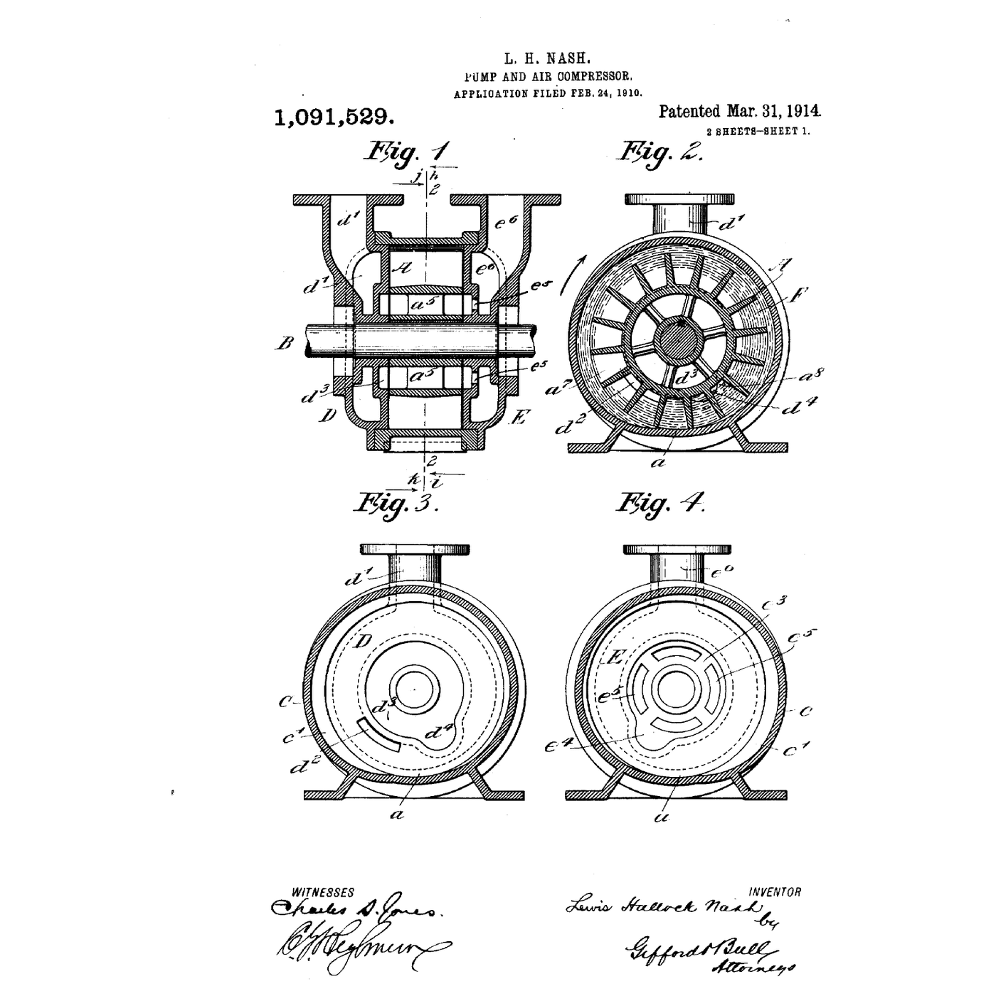

The Liquid-Ring Pump: The Water Is the Piston
A bladed wheel spins off-centre in a round casing partly filled with water. The spin throws the water outward into a ring that follows the casing wall. Because the wheel is off-centre, the ring is deep between the blades on one side and shallow on the other — so each space between two blades fills with water, empties, and fills again once per turn. Each emptying draws gas in; each refilling pushes it out. The water is the piston, and nothing rubs.
Lewis Hallock Nash's patent of 1914 is the form that went into production. It will pump wet gas, dirty gas, vapour that condenses and even slugs of liquid without harm, and the ring cools the gas as it compresses it. That makes it the standard vacuum pump for paper machines, power-station condensers and chemical plant.
It also has a hard floor: it cannot pump below the vapour pressure of its own ring. This rung builds a see-through model and measures that floor.
Orta
About 6 hours
Talimatlar
1
1
One bucket, one revolution: Nash's cycle as a sequence
One bucket, one revolution: Nash's cycle as a sequence
Blockly Çalışma Alanı
Loading Blockly workspace...
2
2
Print the impeller and set it off-centre in a clear casing
Print the impeller and set it off-centre in a clear casing
Use a length of clear acrylic tube of about 100 mm bore as the casing, closed by two acrylic end plates bolted through with machine screws and sealed with O-rings in printed grooves.
Print a 12-bladed impeller in PETG, 80 mm across, with radial blades and a hub for a steel shaft. Make it the full width of the casing less 0.5 mm, so each blade nearly touches both end plates — the end plates are where the gas ports are, and a large side gap lets the gas short-circuit from outlet back to inlet.
Mount the shaft in bearings in the end plates **8 mm off the casing's centre**, so the impeller nearly touches the casing at the top and clears it by about 18 mm at the bottom. Nash put the variation in the casing shape instead — the enlarged lobe — but the effect on the water ring is the same.
Bu adım için malzemeler:
 Akrilik boru (şeffaf)1 adet
 Akrilik Levha1 yaprak
 PETG filament90 g
 Ham çelik çubuk1 adet
 Kaykay rulmanları2 adet
 O-Ring Çeşit Seti1 takım
 Makine vidaları12 adet
Gerekli aletler:
 FDM 3B yazıcı
 Kablosuz Matkap
 Matkap Ucu Takımı
 Dijital Kumpas 6 İnç
 Alyan takımı
3
3
Cut the ports in the right place
Cut the ports in the right place
The ports are crescent-shaped slots in one end plate, close to the hub, and their position is the whole design.
- The **inlet** slot goes where the ring is moving AWAY from the hub — where the buckets are emptying — covering the arc from just past the close point to the bottom.
- The **discharge** slot goes where the ring is moving back IN — where the buckets are filling — ending just before the close point.
- Between the end of one slot and the start of the other, leave solid plate at least one blade-spacing wide at each end, so that no bucket is ever open to both at once.
Mark the direction of rotation on the plate before you cut. The same pump turned backwards blows out of its inlet.
Fit a hose tail to each slot through a printed manifold and seal it with silicone. Tee the vacuum gauge into the inlet hose.
Bu adım için malzemeler:
 Silikon Dolgu Macunu1 adet
 Şeffaf vinil hortum1 metre
 Hortum kelepçesi takımı1 takım
 Vakum göstergesi1 adet
Gerekli aletler:
Kablosuz MatkapMatkap Ucu Takımı Silinmez Kalem
 Cetvel
4
4
Run it, and watch the ring
Run it, and watch the ring
Fill the casing to about a third with water with a drop of dye in it, and drive the shaft with the cordless drill. Below a certain speed the water simply sloshes. Above it the water climbs the wall and forms a ring, and you can see it: deep at the bottom, thin at the top, and the buckets emptying and filling as they pass.
Close the inlet hose with your thumb and read the gauge. Increase the speed and read it again. Then feed the service water: lead a slow trickle of cold water into the inlet side and let the discharge carry the surplus out with the air into a bucket. Measure the temperature of the water leaving.
Then do the test that matters: run once with cold water, once with warm. The warm ring will not reach the same vacuum however fast you drive it — the notebook in the next step says exactly how far it will get.
Bu adım için malzemeler:
 Su10 litre
 Gıda boyası (akış görselleştirme boyası)1 damla
Gerekli aletler:
Kablosuz Matkap Dijital Takometre
 Mutfak termometresi
 Kova
Kova Şeffaf Koruyucu Gözlük
5
5
Vapour pressure sets the floor; heat moves it
Vapour pressure sets the floor; heat moves it
Jupyter defteri yükleniyor…
6
6
The vacuum is poor: find out why
The vacuum is poor: find out why
The faults behind a liquid-ring pump that will not pull down, in the order to check them.
Flow
Loading...
7
7
History and context
History and context
**US 1,091,529, 'Pump and Air Compressor', Lewis Hallock Nash of New York, assignor to the Nash Engineering Company; filed 24 February 1910, patented 31 March 1914.** The specification describes a wheel turning in a cylindrical case chamber with an enlarged portion or *"lobe"*: the water in a bucket *"is caused to flow out into said enlargement by the centrifugal force of the revolving wheel"*, leaving an opening *"through which air or other gas can be drawn"*, and returns as the lobe contracts to eject it.
Nash founded the Nash Engineering Company in 1905, in Norwalk, Connecticut; the Nash name is still on liquid-ring pumps today.
The liquid ring's great virtue is what it tolerates. Gas saturated with water vapour is no problem — the vapour condenses into the ring. Particles pass through. A slug of liquid is simply added to the ring. That is why it drains the water from the felts of paper machines and holds the vacuum on steam condensers, where a dry pump would drown.
**Honest limits.** Its efficiency is low: much of the shaft power churns the ring. The vapour pressure of the service liquid caps the vacuum. It needs a supply of service liquid and gets rid of warm effluent. And the service liquid mixes with what is pumped, so if the gas is toxic, the water becomes a waste stream to treat.
Malzemeler
13- 1 adetYer Tutucu
- 1 yaprakYer Tutucu
- 90 gYer Tutucu
- 1 adetYer Tutucu
- Kaykay rulmanları%10 komisyon2 adetYer Tutucu
- 1 takımYer Tutucu
- 12 adetYer Tutucu
- 1 adetYer Tutucu
- 1 metreYer Tutucu
- 1 takımYer Tutucu
- 1 adetYer Tutucu
- 10 litreYer Tutucu
- Yer Tutucu
Gerekli Aletler
11- Yer Tutucu
- 1 vendor sell this, none ship to you yetYer Tutucu
- Yer Tutucu
- Yer Tutucu
- Yer Tutucu
- Yer Tutucu
- Yer Tutucu
- Yer Tutucu
- Yer Tutucu
- Yer Tutucu
- Yer Tutucu
İlgili Blueprint'ler
Bu blueprint'ler bilgi paylaşır — teknikler, malzemeler veya ilkeler
Rotary Vane Vacuum Pump
Emma tarafından
TEKNOLOJİ
40
0
0
0
0
0
Guericke Air Pump
Penny tarafından
TEKNOLOJİ
49
0
0
0
0
0
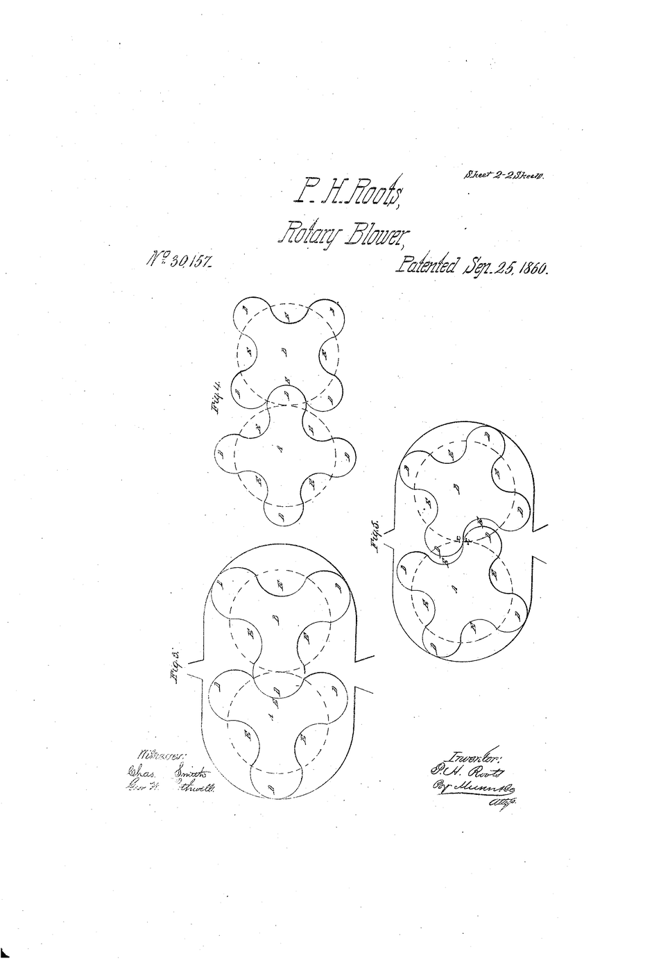
Roots Blower
Karen tarafından
Mekanik
39
0
0
0
0
0
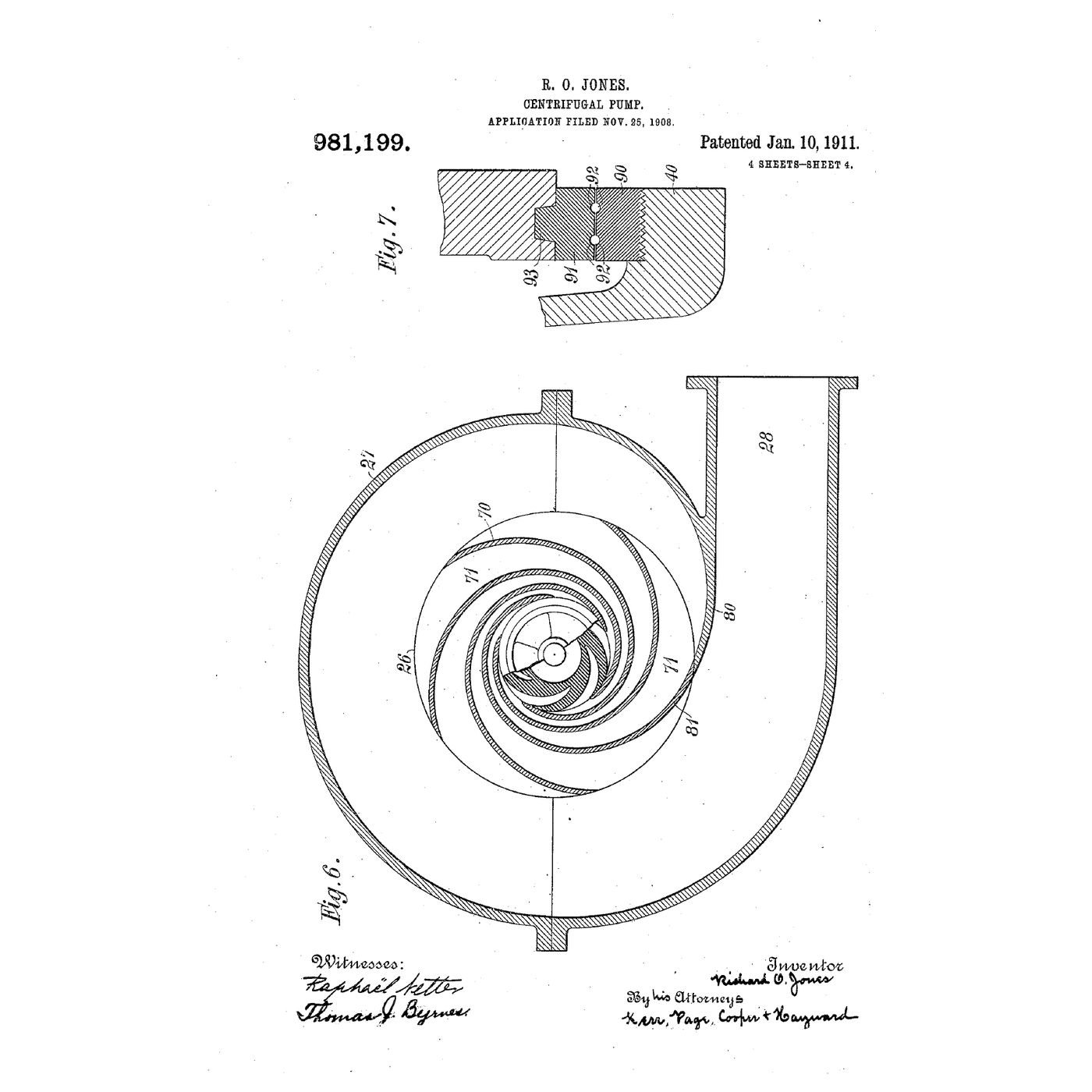
The Centrifugal Pump: Speed Squared, and Why It Cannot Lift Air
Emma tarafından
Mekanik
15
0
0
0
0
0
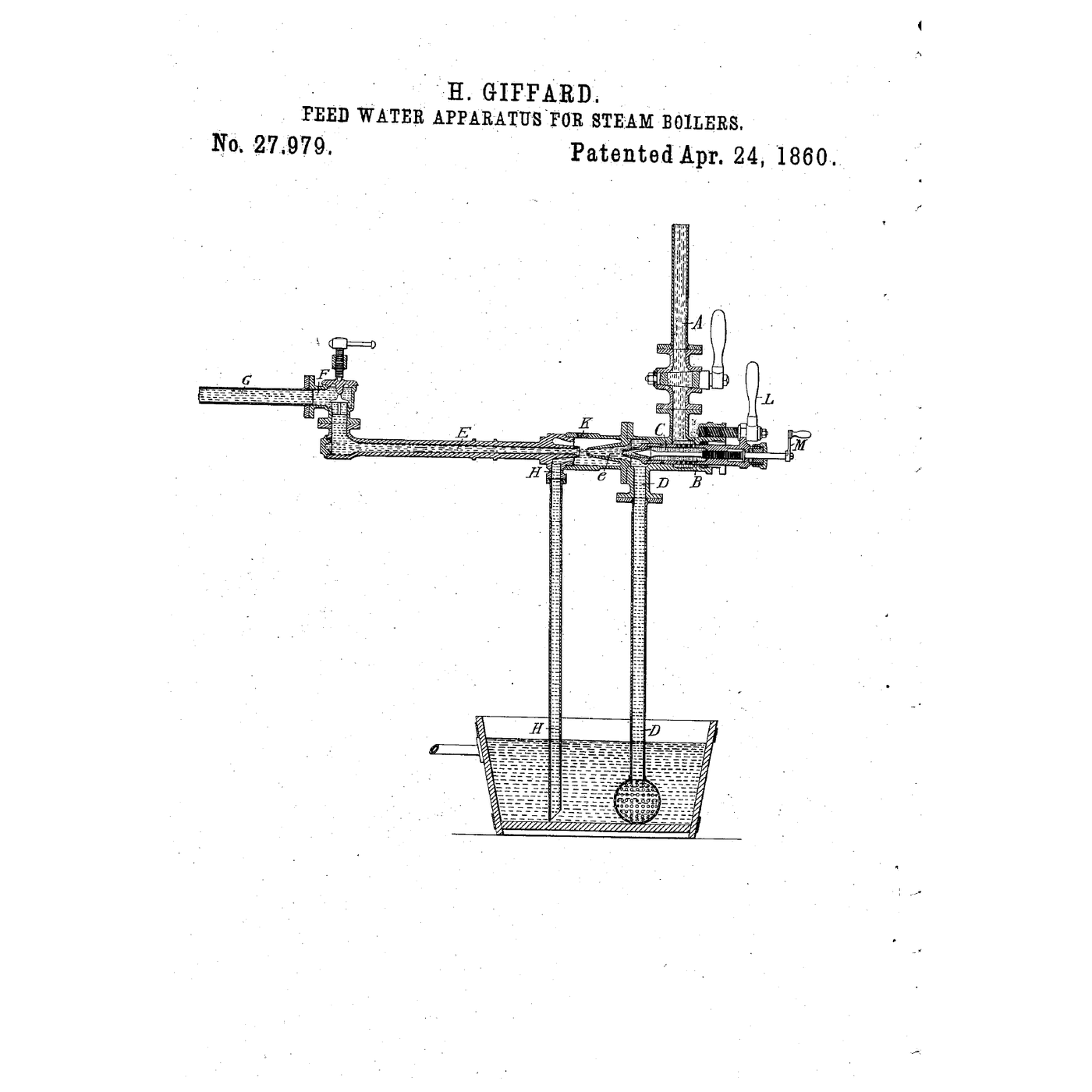
The Steam Injector: Feeding a Boiler With Its Own Steam
Martin tarafından
Mekanik
10
0
0
0
0
0
CC0 Kamu Malı
Bu plan CC0 lisansıyla yayınlanmıştır. İzin almadan kopyalayabilir, değiştirebilir, dağıtabilir ve herhangi bir amaçla kullanabilirsiniz.
Planı üzerinden ürün satın alarak Maker'ı destekleyin, böylece Maker Komisyonu Satıcılar tarafından belirlenen komisyonu kazanırlar veya bu Planın yeni bir versiyonunu oluşturun ve gelir paylaşımı için kendi Planınıza bağlantı olarak ekleyin.