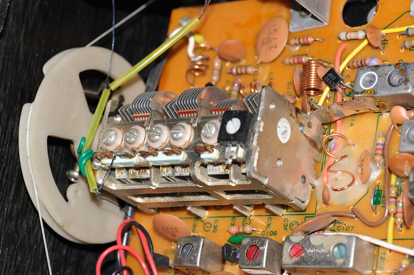


The Tuned Circuit
Talimatlar
Make energy slosh, and watch it decay
Make energy slosh, and watch it decay
Before tuning anything, see the oscillation itself.
- Wind roughly 60 turns of enamelled wire on a 30 mm former to make an air-cored inductor.
- Connect a capacitor of about 300 pF across it.
- Charge the capacitor briefly from a low-voltage supply, then disconnect it and watch across the pair with the oscilloscope.
- Measure the frequency of what you see, and how many cycles it takes to die away.
You will see a decaying sine wave — a ring. Energy is passing back and forth: the capacitor discharges into the coil, building a magnetic field; the field collapses and recharges the capacitor with the opposite polarity; and round again. Nothing drives it. It is the electrical twin of a struck bell, and it decays for the same reason — resistance is quietly converting the energy to heat.
Count the cycles before the amplitude halves and keep that number. It is a direct measure of how lossy your circuit is, and in the next step it turns out to be the single most important property the circuit has.Bu adım için malzemeler:
 Emaye Kaplı Bakır Tel10 m
 Kondansatör Seti1 takım
 Plastik şekillendirme mandreli1 adet
Gerekli aletler:
 Osiloskop
 Ayarlanabilir Tezgâh Güç Kaynağı
 Laboratuvar Sınıfı Dijital Multimetre
 Masaüstü LCR ölçer
 Dijital Kumpas 6 İnç
 Havya İstasyonu
 Şeffaf Koruyucu Gözlük
Sweep it, and measure the Q you just estimated
Sweep it, and measure the Q you just estimated
Now drive the circuit instead of striking it, and find its response curve.
- Couple a signal generator loosely to the coil — one or two turns of wire alongside it is enough.
- Sweep the frequency and record the amplitude across the tuned circuit at each step.
- Plot amplitude against frequency.
- Find the peak, then find the two frequencies where amplitude has fallen to 0.707 of the peak. Divide the peak frequency by the gap between them.
That number is Q, and it is the whole story of selectivity. A high-Q circuit has a tall narrow peak and ignores its neighbours; a low-Q circuit has a broad lump and lets everything through. Notice that Q measured this way agrees with the decay you counted in step 1 — a bell that rings for a long time is a bell with a sharp pitch, and the two are the same fact seen from either side.
Loose coupling is not a convenience, it is a requirement. Couple the generator tightly and its own low impedance is dragged across your circuit, damping it and giving you a Q reading that mostly describes your test equipment.
Reverse-engineering note: this is why radio coils are wound with thick wire, on low-loss formers, spaced apart rather than crammed, and never near a metal chassis. Every one of those choices is fighting for Q, and Q is bought entirely by reducing losses.Bu adım için malzemeler:
Emaye Kaplı Bakır Tel5 mKondansatör Seti1 takım Milimetrik Kağıt1 pad
Gerekli aletler:
 Sinyal ÜreteciOsiloskop
 Spektrum Analizörü / FFT YazılımıMasaüstü LCR ölçerLaboratuvar Sınıfı Dijital MultimetreŞeffaf Koruyucu Gözlük
Make it tunable, and find out what varies
Make it tunable, and find out what varies
A fixed resonance receives one station. Making it sweep is what makes it a radio.
- Replace the fixed capacitor with a variable one and confirm the peak moves as you turn it.
- Record resonant frequency against capacitance across the full range.
- Now instead keep the capacitor fixed and vary the inductance by sliding a ferrite slug into the coil. Record again.
- Compare the two tuning ranges.
Frequency varies with the inverse square root of both inductance and capacitance — so to double the frequency you must quarter one of them. That square-root relationship is why tuning dials are so unevenly spaced, with stations crowded at one end.
Both methods are used in practice and the choice is mechanical rather than electrical. Variable capacitors are bulky, expensive and beautiful; ferrite slug tuning is cheap, compact and used in almost every mass-produced receiver. The physics does not care which one you vary, and that is worth noticing — when two parameters have the same effect, pick the one that is easier to build.Bu adım için malzemeler:
 Ayarlı kondansatör (hava yalıtkanlı)1 adet
 Ferrit toroid çekirdek2 adetEmaye Kaplı Bakır Tel5 m
Gerekli aletler:
Sinyal ÜreteciOsiloskopMasaüstü LCR ölçer Izgara düşümlü osilatör (grid-dip)Dijital Kumpas 6 İnçHavya İstasyonuŞeffaf Koruyucu Gözlük
Discover that selectivity and fidelity are enemies
Discover that selectivity and fidelity are enemies
This is the trade that shapes every receiver ever designed, and it is easy to miss until you measure it.
- Build a high-Q tuned circuit and measure its bandwidth as in step 2.
- Feed it a signal that is amplitude-modulated with an audio tone, and recover the audio.
- Now raise the modulating tone toward the edge of the circuit’s bandwidth and listen to what happens to it.
- Deliberately spoil the Q by adding a resistor across the circuit, and repeat.
The sharp circuit rejects interference beautifully and also strangles the higher audio frequencies; the broad one sounds better and lets the neighbouring station through. The reason is that a modulated carrier is not a single frequency — it occupies a band, and a tuned circuit narrower than that band amputates part of the signal.
So a receiver cannot simply be made as sharp as possible. It needs a bandwidth matched to the signal it is meant to receive, and no sharper. Selectivity and fidelity are a single dial with two labels.
This is exactly why AM broadcast sounds dull and FM does not: the channel allocations differ by an order of magnitude in bandwidth. It is also why a chain of several coupled tuned circuits eventually replaced the single one — several moderate circuits in series can approximate a flat-topped, steep-sided response that no single circuit can produce.Bu adım için malzemeler:
Kondansatör Seti1 takım Direnç Seti1 takımEmaye Kaplı Bakır Tel5 mMilimetrik Kağıt1 pad
Gerekli aletler:
Sinyal ÜreteciOsiloskopSpektrum Analizörü / FFT YazılımıLaboratuvar Sınıfı Dijital MultimetreHavya İstasyonuŞeffaf Koruyucu GözlükBuild a crystal set and hear the whole argument working
Build a crystal set and hear the whole argument working
Assemble the minimum complete radio: an antenna, a tuned circuit, a detector and an earpiece. No power supply of any kind.
- Run a long wire antenna as high and as clear as you safely can, and provide a good earth.
- Couple it to your tuned circuit through a small capacitor or a few turns of link coupling.
- Connect a germanium diode as detector, feeding a high-impedance crystal earpiece with a small capacitor across it.
- Tune slowly across the band and log what you hear against dial position.
The entire energy reaching your ear was transmitted by a station possibly hundreds of kilometres away and captured by your wire. There is no amplification anywhere in this circuit — which is precisely why the tuned circuit’s Q matters so much here, and why the next blueprint, regeneration, was such an enormous step.
Notice the antenna coupling. Connect the antenna directly across the tuned circuit and it will load it heavily, wrecking the Q and blurring the tuning; couple it loosely and selectivity returns but signals weaken. That trade-off is real and unavoidable, and the tap position on the coil is where it gets settled.
Never run an antenna near power lines, and disconnect and earth it in a thunderstorm. A long wire is an efficient collector of atmospheric energy, which is the point, and lightning is atmospheric energy.Bu adım için malzemeler:
Emaye Kaplı Bakır Tel30 m Germanyum diyot (1N34A)2 adet
 Kristal kulaklık (yüksek empedanslı)1 adetAyarlı kondansatör (hava yalıtkanlı)1 adet
 Delikli Plaket / Prototip Plaketi1 adet
 63/37 reçine özlü lehim teli1 reel
Gerekli aletler:
Havya İstasyonuLaboratuvar Sınıfı Dijital MultimetreOsiloskopDijital Kumpas 6 İnçŞeffaf Koruyucu GözlükMalzemeler
11- Yer Tutucu
- 1 takımYer Tutucu
- Yer Tutucu
- 1 padYer Tutucu
- Yer Tutucu
- 2 adetYer Tutucu
- Yer Tutucu
- 2 adetYer Tutucu
- Yer Tutucu
- Yer Tutucu
- Yer Tutucu
Gerekli Aletler
10- Yer Tutucu
- Yer Tutucu
- Yer Tutucu
- Yer Tutucu
- Yer Tutucu
- Yer Tutucu
- Yer Tutucu
- Yer Tutucu
- Yer Tutucu
- Yer Tutucu
İlgili Blueprint'ler
Bu blueprint'ler bilgi paylaşır — teknikler, malzemeler veya ilkeler


CC0 Kamu Malı
Bu plan CC0 lisansıyla yayınlanmıştır. İzin almadan kopyalayabilir, değiştirebilir, dağıtabilir ve herhangi bir amaçla kullanabilirsiniz.
Planı üzerinden ürün satın alarak Maker'ı destekleyin, böylece Maker Komisyonu Satıcılar tarafından belirlenen komisyonu kazanırlar veya bu Planın yeni bir versiyonunu oluşturun ve gelir paylaşımı için kendi Planınıza bağlantı olarak ekleyin.