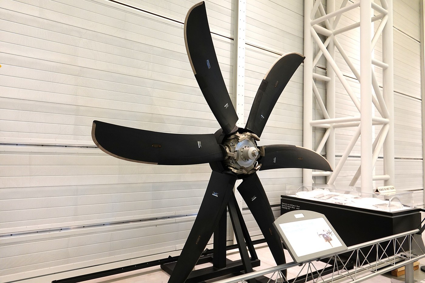


The Variable-Pitch Propeller
Talimatlar
Measure the compromise you are trying to escape
Measure the compromise you are trying to escape
Quantify the loss before engineering it away.
- Take two fixed propellers of the same diameter but different pitch — one fine, one coarse.
- On the thrust rig, measure static thrust and rpm for each at full power.
- Now measure both in the wind tunnel at a simulated cruise airspeed, recording thrust and rpm.
- Tabulate all four results.
The fine propeller wins at zero airspeed and overspeeds the motor at cruise; the coarse one is feeble static and efficient at speed. Neither is good at both, and the gap between them is the performance a fixed propeller throws away.
This is exactly the reasoning behind gears on a bicycle, and the analogy is worth keeping: fine pitch is a low gear for accelerating, coarse pitch is a high gear for cruising. The engine, like a cyclist, has one narrow band of speed where it makes its best power, and the propeller’s job is to keep it there.Bu adım için malzemeler:
 Milimetrik Kağıt1 pad
Gerekli aletler:
 Yaylı Terazi
 Dijital Takometre
 El anemometresi
 Dijital Kumpas 6 İnç
 İletki
 Şeffaf Koruyucu Gözlük
Build a hub whose blades can rotate
Build a hub whose blades can rotate
The whole mechanism is a blade root that turns in a bearing while transmitting enormous loads.
- Turn a cylindrical hub with two radial bores, one per blade.
- Machine each blade root as a matching shank with a shoulder that seats against a thrust bearing.
- Fit each root with a needle or ball thrust bearing so it can rotate under load.
- Attach a short crank pin to the inboard end of each blade root, offset from the rotation axis.
- Confirm each blade turns smoothly through at least 30° with no radial play.
The thrust bearing is doing the difficult work: it must let the blade twist freely while carrying the full centrifugal load, which on a real propeller is measured in tonnes. Radial play is unacceptable — any slop becomes a blade angle that varies with load, which is exactly the imprecision the mechanism exists to remove.
Reverse-engineering note: blade roots on real propellers are round and surprisingly thick for their aerodynamic contribution, and this is why. The root is a structural and bearing component first, and the fact that it also has to be an aerofoil is a distant secondary concern.Bu adım için malzemeler:
 Alüminyum yuvarlak çubuk1 adet
 Eksenel rulman (iğneli)2 adet
 Bilyalı Rulman2 adet
 M5 silindir başlı vidalar8 adet
Gerekli aletler:
 Metal Torna Tezgâhı
 4 İnç Freze Mengenesi
 Sütunlu Matkap
 Komparatör SaatiDijital Kumpas 6 İnç
 Mikrometre
 Tork AnahtarıŞeffaf Koruyucu Gözlük
Drive both blades together from one actuator
Drive both blades together from one actuator
Two blades that disagree about their pitch are worse than two blades that are both wrong.
- Make a sliding yoke inside the hub, free to move along the shaft axis.
- Cut a slot in the yoke to engage each blade’s crank pin.
- Confirm that moving the yoke axially rotates both blades by the same amount, in the same direction.
- Measure both blade angles with an angle gauge at three yoke positions and check they agree within a fraction of a degree.
Converting axial motion into synchronised rotation is the mechanical heart of it, and the same slot-and-crankpin arrangement appears in almost every real design. One actuator, one yoke, all blades identical by construction rather than by adjustment.
If the blades disagree, the propeller produces asymmetric thrust and a vibration once per revolution — indistinguishable at first from an imbalance, and traceable only by measuring each blade angle individually. Build the check into the assembly rather than diagnosing it later.Bu adım için malzemeler:
Alüminyum yuvarlak çubuk1 adet Çelik pim4 adetM5 silindir başlı vidalar4 adet
Gerekli aletler:
Metal Torna Tezgâhı4 İnç Freze MengenesiKomparatör Saati Dijital Açı ÖlçerDijital Kumpas 6 İnçTork AnahtarıŞeffaf Koruyucu Gözlük
Let centrifugal force fight a spring, and get a governor
Let centrifugal force fight a spring, and get a governor
Now make it adjust itself, which is where it stops being a mechanism and becomes a control system.
- Fit a pair of flyweights to the hub, hinged so that spinning throws them outward.
- Link the flyweights to the sliding yoke so that outward movement drives the blades toward COARSE pitch.
- Oppose them with a compression spring whose preload you can adjust.
- Spin the assembly and observe blade angle against rpm.
- Change the spring preload and repeat.
The propeller now holds a roughly constant speed on its own. If rpm rises, the flyweights swing out, pitch coarsens, the blades take a bigger bite, the load on the engine increases and rpm falls back. If rpm drops, the spring wins, pitch fines off, load decreases and rpm recovers. The spring preload sets the target speed — which is exactly what the blue-knobbed propeller lever in the cockpit adjusts.
It is a negative-feedback governor, mechanically identical in principle to the flyball governor on a steam engine. The error signal is rotational speed, the correction is blade angle, and no electronics are involved anywhere.
Watch for hunting: if the response is too aggressive the system overshoots, corrects too far, and oscillates. Real constant-speed units damp this with restricted oil flow. On the bench, more spring preload and more friction in the yoke both help — and diagnosing hunting is itself worth the experiment, because it is the characteristic failure of every feedback loop ever built.Bu adım için malzemeler:
 Basma yay takımı1 takımÇelik pim4 adet
 Alüminyum Plaka1 adet
Gerekli aletler:
Metal Torna Tezgâhı4 İnç Freze MengenesiDijital TakometreDijital Açı ÖlçerDijital Kumpas 6 İnçKomparatör SaatiŞeffaf Koruyucu GözlükFeather it, and understand the failure it prevents
Feather it, and understand the failure it prevents
The most valuable blade angle is the one that produces no thrust at all.
- Extend the pitch range so the blades can rotate to roughly 90° — edge-on to the airflow.
- With the rig in the tunnel and the motor unpowered, measure the drag at normal pitch.
- Now rotate the blades to the feathered position and measure again.
A stopped propeller at normal pitch is a large flat disc of drag; feathered, it is a few knife-edges. The difference is dramatic, and on a twin-engined aircraft it is the difference between flying on one engine and descending on one engine.
Worse than the drag is what an unfeathered propeller does while windmilling: the airflow spins it, it drags the dead engine round with it, and it produces a large asymmetric drag on one wing that must be held off with rudder. Feathering removes the drag and stops the rotation together.
The opposite extreme is equally useful. Rotate the blades past fine into NEGATIVE pitch and the propeller pushes air forward — reverse thrust, which is what turboprops use to stop on short runways, and what lets a floatplane back off a jetty. The same mechanism, asked for an angle outside its normal range, becomes a brake.Bu adım için malzemeler:
Basma yay takımı1 takımMilimetrik Kağıt1 padGerekli aletler:
Yaylı TeraziEl anemometresiDijital Açı ÖlçerDijital TakometreDijital Kumpas 6 İnç Ağır Çekim Video Çeken Akıllı TelefonŞeffaf Koruyucu Gözlük
Malzemeler
8- 1 padYer Tutucu
- 1 adetYer Tutucu
- 2 adetYer Tutucu
- şu fiyattan$1.26
- 12 adetYer Tutucu
- 4 adetYer Tutucu
- 1 takımYer Tutucu
- 1 adetYer Tutucu
Gerekli Aletler
14- Yer Tutucu
- Yer Tutucu
- Yer Tutucu
- Yer Tutucu
- Yer Tutucu
- Yer Tutucu
- Yer Tutucu
- Yer Tutucu
- Yer Tutucu
- Yer Tutucu
- Yer Tutucu
- Yer Tutucu
- Yer Tutucu
- Yer Tutucu
İlgili Blueprint'ler
Bu blueprint'ler bilgi paylaşır — teknikler, malzemeler veya ilkeler
CC0 Kamu Malı
Bu plan CC0 lisansıyla yayınlanmıştır. İzin almadan kopyalayabilir, değiştirebilir, dağıtabilir ve herhangi bir amaçla kullanabilirsiniz.
Planı üzerinden ürün satın alarak Maker'ı destekleyin, böylece Maker Komisyonu Satıcılar tarafından belirlenen komisyonu kazanırlar veya bu Planın yeni bir versiyonunu oluşturun ve gelir paylaşımı için kendi Planınıza bağlantı olarak ekleyin.