Співпраця
МИСТЕЦТВО
КРАСА ТА ЗДОРОВ'Я
РЕМЕСЛО
КУЛЬТУРА ТА ІСТОРІЯ
РОЗВАГИ
СЕРЕДОВИЩЕ
ЇЖА ТА НАПІЇ
ЗБОРНА ІНЖЕНЕРІЯ
НАУК
СПОРТ
ТЕХНОЛОГІЯ
НОСИМО
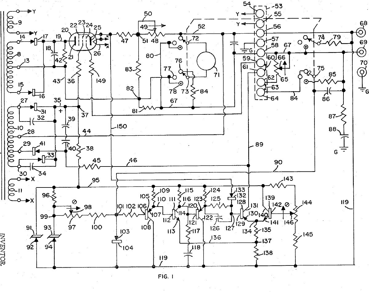


Bench Power Supply: Regulated, with Adjustable Current Limit and a Pentode Pass Tube (Gately, Forbro, US 3,243,690, 1966)
An adjustable bench supply that holds its output voltage steady and lets you set the most current it will deliver, so a circuit under test cannot be damaged. A pentode tube in series with the output is the regulator; a bridge with Zener references and a five-transistor amplifier keeps the output equal to the setting of one knob. A meter switch reads volts, amps, and the current limit, which can be set without disturbing the voltage.
Result: a regulated DC bench supply with adjustable current limiting.
Source: J. R. Gately (Forbro Design), US 3,243,690 (1966). Unknown: all component values and the output rating. Picture: the patent drawing.
Просунутий
Unknown
Інструкції
1
1
Wire the mains side
Wire the mains side
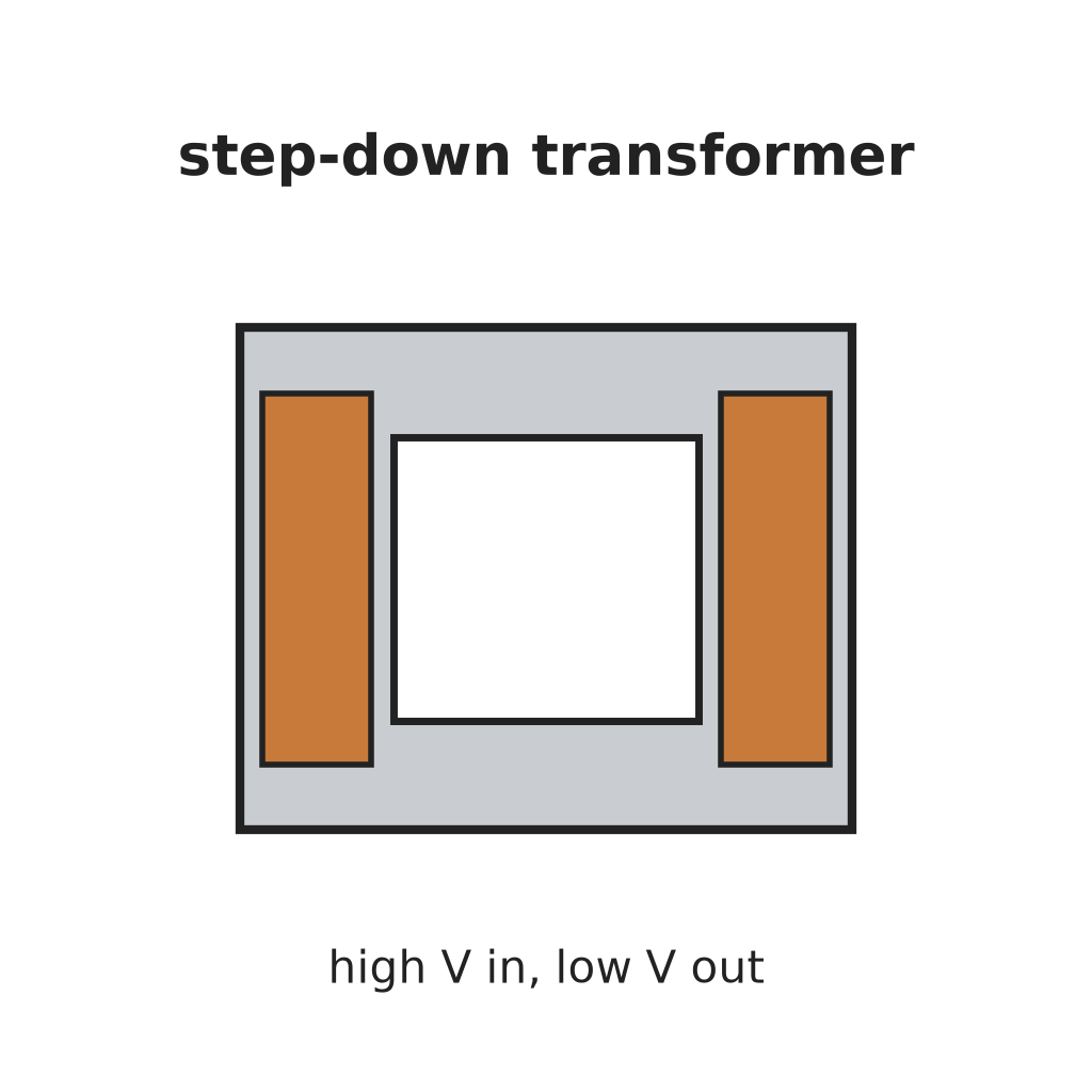
In a case, wire the power cord through a switch and a fuse to the primary of a transformer with four secondaries, and put a neon lamp across the primary to show the supply is on. One secondary (6.3 V) goes to two terminals for outside use, one heats the pentode, one is the main supply and one the bias supply. Ours: the case. Not given: the other winding voltages.
Матеріали для цього кроку:
 Алюмінієвий корпус1 case
 Гнучкий шнур із вилкою1 штука
 Тумблер1 штука
 Плавкий запобіжник1 штука
 Знижувальний трансформатор1 four secondaries
 Неонова індикаторна лампа1 штука
 Клема-барашок2 6.3 V terminals
Необхідні інструменти ({count})
 Ручний дриль
 Набір викруток
2
2
Build the rectifiers
Build the rectifiers
Rectify the centre-tapped main winding with two rectifiers and smooth it with a capacitor. From the bias winding make two more supplies: one through two rectifiers with by-pass capacitors to a smoothing capacitor, for the pentode's screen and the reference circuit; the other through one rectifier and a capacitor, for the pentode's grid bias. Not given: the values.
Матеріали для цього кроку:
 Діод5 rectifiers
 Електролітичний конденсатор3 smoothing
 Набір конденсаторів1 by-pass
 Дріт припою1 as needed
Необхідні інструменти ({count})
 Паяльник
3
3
Fit the pass tube and reference
Fit the pass tube and reference
Put the pentode in series with the positive output: plate to the main supply, cathode through two current-sensing resistors (one fixed, one adjustable) to the + output terminal; suppressor tied to the cathode, screen fed through a resistor. Build the reference: a Zener fed through a resistor feeds a second Zener at constant current, giving a fixed voltage. Against it set two resistors and the voltage-control variable resistor: the output voltage is proportional to that resistor's setting. Not given: the tube type and values.
Матеріали для цього кроку:
 Пентодна лампа1 series pass tube
 Стабілітрон2 штук
 Опір1 набір
 Реостат2 voltage control, current-limit rangeКлема-барашок2 output + and -Дріт припою1 as needed
Необхідні інструменти ({count})
Паяльник4
4
Build the error amplifier and current limit
Build the error amplifier and current limit
Build a five-transistor amplifier that drives the pentode's grid to keep the bridge balanced: a PNP emitter follower, an NPN stage, a PNP emitter follower with a resistor-capacitor roll-off against oscillation, a PNP driver whose base resistor has a capacitor across it for quick response, and an NPN clamp whose base is set by a potentiometer. Feed the voltage across the current-sensing resistors to the driver's base through a diode: above the limit it takes over and turns the pentode down. Choose the fixed sensing resistor to limit at about 125 % of rated current, trim with the potentiometer, and use the adjustable one to set lower limits. Not given: the transistor types and values.
Матеріали для цього кроку:
 Транзистор p-n-p3 штук
 Транзистор NPN2 штукДіод1 штука
 Потенціометр1 штукаНабір конденсаторів1 roll-off, speed-upОпір1 набірДріт припою1 as needed
Необхідні інструменти ({count})
Паяльник5
5
Fit the meter and use it
Fit the meter and use it
Fit a meter with a four-pole, three-position switch. Position 1 reads output volts through a multiplier resistor; position 2 reads current across a shunt in the negative line; position 3 (spring-return) puts a load resistor across the output and swaps a fixed resistor for the voltage control, so you can turn the limit control until the current limits at the value you want, without touching the voltage setting. Release the switch and use the supply.
Матеріали для цього кроку:
 Щитовий прилад магнітоелектричної системи1 штука
 Галетний перемикач1 4-pole, 3-positionОпір1 multiplier, shunt, load resistors
 Невідомий матеріал1 terminal strip
Необхідні інструменти ({count})
ПаяльникНабір викрутокМатеріали
21- 1 caseЗаповнювач
- 1 штукаЗаповнювач
- Заповнювач
- 1 штукаЗаповнювач
- 1 four secondariesЗаповнювач
- 1 штукаЗаповнювач
- Заповнювач
- 1 штукаЗаповнювач
- 3 smoothingЗаповнювач
- 1 roll-off, speed-upЗаповнювач
- 3 as neededЗаповнювач
- 1 series pass tubeЗаповнювач
- 2 штукЗаповнювач
- 1 multiplier, shunt, load resistorsЗаповнювач
- 2 voltage control, current-limit rangeЗаповнювач
- 3 штукЗаповнювач
- 2 штукЗаповнювач
- Заповнювач
- Заповнювач
- 1 4-pole, 3-positionЗаповнювач
- 1 terminal stripЗаповнювач
За цим кресленням виготовляють

CC0 Суспільне надбання
Це креслення випущено під ліцензією CC0. Ви можете вільно копіювати, змінювати, поширювати та використовувати цю роботу для будь-яких цілей без запиту дозволу.
Підтримайте мейкера, купуючи продукти через його креслення, де він отримує Комісію мейкера встановлену вендорами, або створіть нову ітерацію цього креслення та включіть його як зв'язок у власне креслення для розподілу доходу.