


Centerless Grinding
Every grinding machine before this one held the work between centres — which means someone first had to drill a centre in each end of each part, and the finished roundness could never be better than those two holes. For a bearing roller 8 mm long, that is absurd.
US 1,210,937, “Roll-Grinding Machine”, Lewis R. Heim of Danbury, Connecticut, assignor to the Ball and Roller Bearing Company. Filed 6 March 1915, granted 2 January 1917. The work is supported on a blade between a fast grinding wheel and a slow regulating wheel turning the other way. It is held by nothing. It finds its own axis, and what the machine removes is whatever stands proud — so the part becomes round because roundness is the only shape that survives the process.
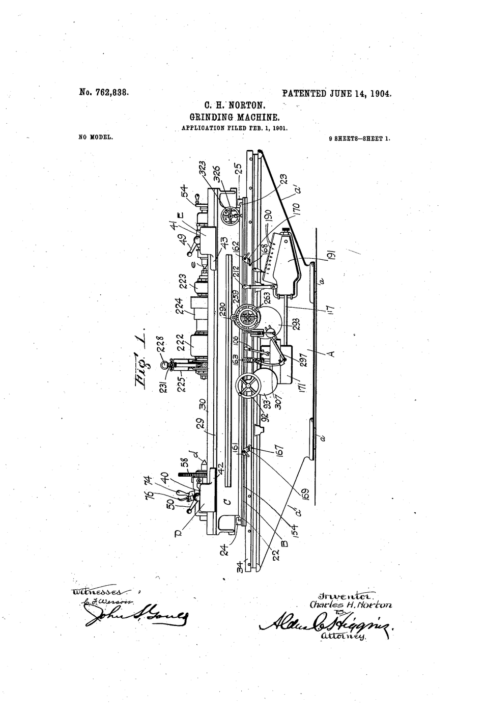
A correction worth making. This patent is very widely cited as US 1,264,928. That is a different Heim patent, for a device that feeds rolls for end-grinding. Note too that the sheet never uses the word “centerless” — the name came later, from the shop floor.
Інструкції
State what centres cost
State what centres cost
Write it down: work held between centres can only be as round as the centre holes, and someone must drill them first. That is two operations before any grinding starts.
Measure a dowel's roundness
Measure a dowel's roundness
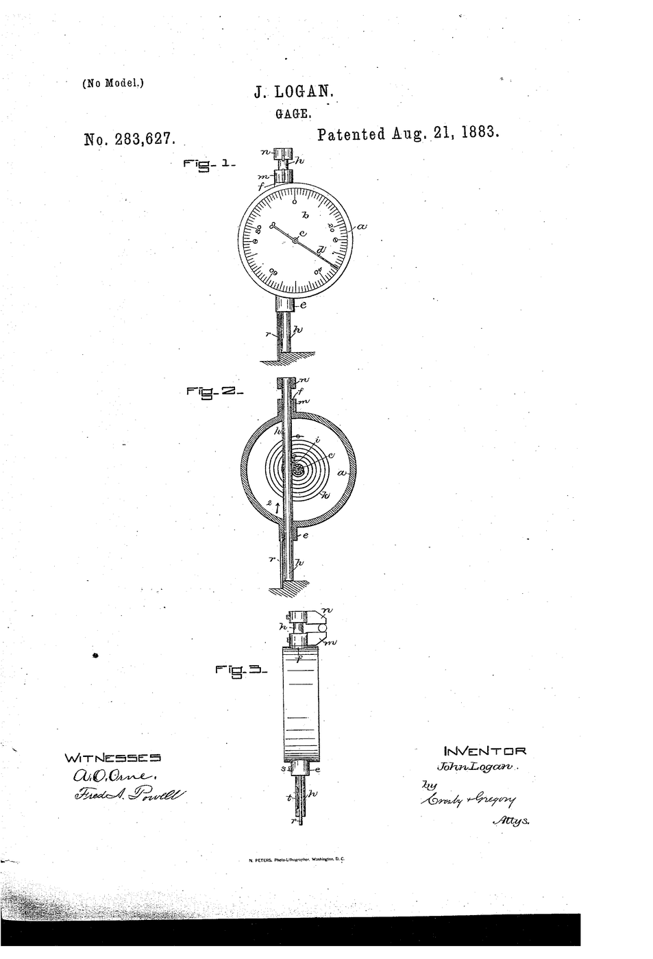
Roll the dowel rod under the dial indicator on the surface plate. Record the needle sweep for one full turn — that is its out-of-roundness.
Матеріали для цього кроку:
 Дерев'яні шканти1 штука
Необхідні інструменти ({count})
 Dial Indicator
 Surface Plate
Cut a work blade
Cut a work blade
Cut a plywood strip 150 × 25 mm and bevel one long edge to about 30° with sandpaper. This is the blade the work rests on.
Матеріали для цього кроку:
 Балтійська березова фанера1 аркуш
 Наждачний папір1 аркуш
Необхідні інструменти ({count})
 Craft Knife
 Protractor
Mount two rollers
Mount two rollers
Fix two dowel rods parallel on the board, 60 mm apart, free to turn. These stand for the grinding wheel and the regulating wheel.
Матеріали для цього кроку:
Дерев'яні шканти2 штук Пласка дерев'яна дошка1 штука
Необхідні інструменти ({count})
 Wood Glue
Set the blade between them
Set the blade between them
Glue the blade upright between the rollers so a third dowel resting on it touches both.
Матеріали для цього кроку:
Балтійська березова фанера1 аркушСтолярний клей10 млНеобхідні інструменти ({count})
 Steel Ruler (30cm)
Set the work above centre
Set the work above centre
Adjust the blade height so the workpiece centre sits above the line joining the two wheel centres. Measure the offset and write it down.
Матеріали для цього кроку:
 Міліметровий папір1 аркуш
Необхідні інструменти ({count})
Steel Ruler (30cm)Turn the rollers and watch the work
Turn the rollers and watch the work
Turn both rollers the same direction by hand. The workpiece spins the opposite way and stays seated on the blade without being held.
Set the work exactly on centre and watch it fail
Set the work exactly on centre and watch it fail
Lower the blade until the work is level with the wheel centres. It now chatters and can lobe. The above-centre offset is not a detail; it is the whole trick.
Матеріали для цього кроку:
Міліметровий папір1 аркушНеобхідні інструменти ({count})
Steel Ruler (30cm)Sand a flat onto a dowel
Sand a flat onto a dowel
Deliberately sand one flat onto a spare dowel. Measure the resulting out-of-roundness with the indicator.
Матеріали для цього кроку:
Дерев'яні шканти1 штукаНаждачний папір1 аркушНеобхідні інструменти ({count})
Dial IndicatorGrind it round by rotation
Grind it round by rotation
Hold sandpaper against the dowel while it rotates on your rig. Because the high spot always presents itself, the flat is removed first.
Матеріали для цього кроку:
Дерев'яні шканти1 штукаНаждачний папір1 аркушRe-measure and record the improvement
Re-measure and record the improvement
Measure the dowel again. Record before and after. The error fell without you ever locating the part.
Матеріали для цього кроку:
Міліметровий папір1 аркушНеобхідні інструменти ({count})
Dial IndicatorAngle the regulating wheel to feed the work
Angle the regulating wheel to feed the work
Tilt one roller a few degrees. The work now walks along the blade as it turns — this is through-feed, and it is why the process is continuous rather than one part at a time.
Необхідні інструменти ({count})
ProtractorCount the operations you removed
Count the operations you removed
List what a centred process needs: face, centre-drill both ends, mount, grind, dismount. List what yours needs: feed. Write the difference down.
Матеріали для цього кроку:
Міліметровий папір1 аркушHistory & Context
History & Context
US 1,210,937, “Roll-Grinding Machine”, Lewis R. Heim, Danbury, Connecticut, assignor to the Ball and Roller Bearing Company of Danbury. Filed 6 March 1915, granted 2 January 1917. The patent describes a high-speed grinding wheel, a carrier for the rolls, and a counter-rotating wheel of relatively low surface speed which ensures “constant and uniform rotation of the rolls”. That second wheel is the regulating wheel, and it is the invention.
The citation error. A great many sources give the foundational centerless patent as US 1,264,928 of 7 May 1918. That document is Heim's, but it is a device for feeding rolls for end-grinding — a magazine and carrier disc, not the centerless principle. The 1915/1917 patent is the right one. Heim went on to take some 28 patents in the field, and Cincinnati Milling Machine acquired the centerless business in 1922.
Why it existed at all: bearings. Heim was working at a ball and roller bearing company, and a bearing roller is the worst possible candidate for centred grinding — short, small, needed by the million, and required to be round to a few microns. The rise of the anti-friction bearing and the rise of centerless grinding are the same industrial event.
The counter-intuitive part. Setting the work above the wheel centres is what makes roundness improve rather than merely persist. On centre, a lobed part can rotate with its lobes tracking, and the machine faithfully reproduces the lobes; above centre, the geometry breaks that symmetry and high spots get cut preferentially. Step 8 is that failure mode made visible.
What it is used for now. Almost anything long, round and made in quantity: bearing rollers, piston pins, valve stems, hydraulic rod, drill blanks, needle stock. Through-feed centerless grinding remains one of the highest-output metal-removal processes in existence.
Матеріали
6- 5 штукЗаповнювач
- 1 аркушЗаповнювач
- 1 аркушЗаповнювач
- 1 штукаЗаповнювач
- 10 млЗаповнювач
- 1 аркушЗаповнювач
Необхідні інструменти
6- Заповнювач
- Заповнювач
- Заповнювач
- Заповнювач
- Заповнювач
- Заповнювач
Матеріали з пов'язаних креслень


Пов'язані креслення
Ці креслення діляться знаннями — техніки, матеріали або принципи
CC0 Суспільне надбання
Це креслення випущено під ліцензією CC0. Ви можете вільно копіювати, змінювати, поширювати та використовувати цю роботу для будь-яких цілей без запиту дозволу.
Підтримайте мейкера, купуючи продукти через його креслення, де він отримує Комісію мейкера встановлену вендорами, або створіть нову ітерацію цього креслення та включіть його як зв'язок у власне креслення для розподілу доходу.