
МИСТЕЦТВО
КРАСА ТА ЗДОРОВ'Я
РЕМЕСЛО
КУЛЬТУРА ТА ІСТОРІЯ
РОЗВАГИ
СЕРЕДОВИЩЕ
ЇЖА ТА НАПІЇ
ЗБОРНА ІНЖЕНЕРІЯ
НАУК
СПОРТ
ТЕХНОЛОГІЯ
НОСИМО
Metal Band Saw: Horizontal Saw on a Welded Steel Frame
Martin

Створено

Martin

23. жовтень 2026NO
5
0
0
0
0

Metal Band Saw: Horizontal Saw on a Welded Steel Frame

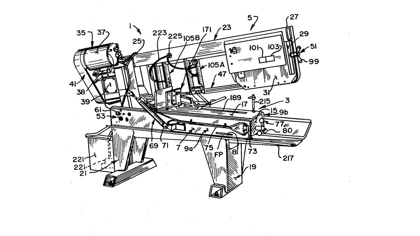
Curtis Eccardt's horizontal power band saw (Emerson Electric, US 4,364,294, 1982), built from welded steel channel and tube instead of iron castings to cut its cost. The saw head swings down on trunnions over the bed; a hydraulic cylinder with a valve sets how fast it feeds, a spring counterbalances it, and a spring tensioner shows the blade tension on a scale. Two guides with rollers twist the blade's lower run 90° so its teeth face down into the work, and carbide inserts hold it there. The patent gives no sizes, speeds or ratings; the welder and wrenches are ours. The picture: the patent's Fig. 1.
Просунутий
4 days

Інструкції

1

Weld the bed

Stand two steel channels (9a, 9b) parallel, webs upright and flanges facing in, and weld gussets (15) between their webs. Bolt a bed plate (17) across the top flanges as the work surface. Ours: MIG welder, drill press for the bolt holes.

Матеріали для цього кроку:

Сталевий швелерСталевий швелер2 штук
Лист маловуглецевої сталіЛист маловуглецевої сталі1 штука
Болт із шестигранною головкою - клас 8.8Болт із шестигранною головкою - клас 8.81 штука

Необхідні інструменти ({count})
Зварювальний напівавтомат MIGЗварювальний напівавтомат MIG
Свердлильний верстатСвердлильний верстат
Розвідний ключРозвідний ключ
2

Weld and bolt on the legs

Weld formed sheet-steel legs onto horizontal floor members to make front and rear leg weldments (19, 21), and bolt them under the bed.

Матеріали для цього кроку:

Сталевий листСталевий лист1 штука
Сталева труба конструкційнаСталева труба конструкційна1 штука
Болт із шестигранною головкою - клас 8.8Болт із шестигранною головкою - клас 8.81 штука

Необхідні інструменти ({count})

Зварювальний напівавтомат MIGЗварювальний напівавтомат MIG
Розвідний ключРозвідний ключ
3

Weld the head

Weld a head post (25) of square or rectangular steel tube square to a head beam (27) of rectangular tube. Weld a bracket leg (29) down from the beam's outer end, and fix support plates at both ends (31, 33).

Матеріали для цього кроку:

Сталева труба конструкційнаСталева труба конструкційна1 штука
Лист маловуглецевої сталіЛист маловуглецевої сталі1 штука

Необхідні інструменти ({count})

Зварювальний напівавтомат MIGЗварювальний напівавтомат MIG
4

Fit the trunnions and align the pivot

Fix a shaft through the head post with its ends out as trunnions (55a, 55b), in bushings in two bearing blocks (59a, 59b) bolted inside the channel webs. Each block has one close-fit bolt hole and three oversize ones: shift the blocks until the pivot is parallel to the bed plate, then torque the bolts. A set screw (67) takes out end play.

Матеріали для цього кроку:

Сталевий валСталевий вал1 штука
Металева втулкаМеталева втулка2 штук
Корпус підшипникаКорпус підшипника2 штук
Болт із шестигранною головкою - клас 8.8Болт із шестигранною головкою - клас 8.88 штук
Установчий гвинт із чашоподібним кінцемУстановчий гвинт із чашоподібним кінцем1 штука

Необхідні інструменти ({count})

Свердлильний верстатСвердлильний верстат
Динамометричний ключДинамометричний ключ
5

Mount motor, belt drive and gearbox

Mount the electric motor (37) on a plate (38) pivoted on the head beam, and couple it by a multi-speed belt and pulleys (41) to a gearbox (39). Fit the drive wheel (43) on the gearbox output shaft.

Матеріали для цього кроку:

ЕлектродвигунЕлектродвигун1 штука
Лист маловуглецевої сталіЛист маловуглецевої сталі1 штука
Приводний пасПриводний пас1 штука
БлокБлок1 штука
РедукторРедуктор1 штука
Шків стрічкової пилкиШків стрічкової пилки1 штука

Необхідні інструменти ({count})

Розвідний ключРозвідний ключ
6

Build the idler tensioner

Weld an idler yoke (87) of rolled steel plate, pivot it on the head beam with a pin (89), and cantilever the idler axle from it with the idler wheel (45) on bearings (85). A threaded rod (91) pulls the yoke through a coil spring (93) held between compression plates and a U-bolt (97); a knob (99) turns the rod. An indicator (101) on the spring reads the tension on a scale (103).

Матеріали для цього кроку:

Лист маловуглецевої сталіЛист маловуглецевої сталі1 штука
Сталевий запресовуваний штифтСталевий запресовуваний штифт1 штука
Сталевий валСталевий вал1 штука
Шків стрічкової пилкиШків стрічкової пилки1 штука
Кульковий підшипникКульковий підшипник1 штука
Шпилька різьбоваШпилька різьбова1 штука
Coil SpringCoil Spring1 штука
Скоба-хомутСкоба-хомут1 штука
Ручка керуванняРучка керування1 штука

Необхідні інструменти ({count})

Зварювальний напівавтомат MIGЗварювальний напівавтомат MIG
Розвідний ключРозвідний ключ
7

Build the two blade guides

In each guide channel (111) mount two guide rollers (115a, 115b) on ball bearings on eccentric bushings, one fixed and one adjusted to the blade thickness. Add a carbide thrust insert (133) on the blade's back edge and two carbide side inserts (137a fixed, 137b on a sprung swing bracket set by a bolt and knob). Clamp the guides on two bar tracks (107).

Матеріали для цього кроку:

Напрямний роликНапрямний ролик4 штук
Кульковий підшипникКульковий підшипник4 штук
Ексцентрикова втулкаЕксцентрикова втулка4 штук
Твердосплавна вставкаТвердосплавна вставка6 штук
Coil SpringCoil Spring2 штук
Ручка керуванняРучка керування2 штук
Сталева труба конструкційнаСталева труба конструкційна1 штука

Необхідні інструменти ({count})

Розвідний ключРозвідний ключ
8

Fit the blade and set the tension

By hand, run the endless blade (47) round the drive and idler wheels and through both guides; the rollers twist its lower run about 90° so the teeth face down. Turn the tension knob until the scale shows the tension you want.

Матеріали для цього кроку:

Полотно стрічкової пилкиПолотно стрічкової пилки1 штука
9

Fit the feed cylinder and counterbalance

Connect a hydraulic cylinder (71) between bed channel and head post above the trunnions, filled with oil and piped through tubing (75) to a control valve (73): the valve sets the feed rate and, closed, holds the head. Fit a coil spring (78) on a threaded linkage (79) between an end gusset and the head post below the trunnions, adjusted by a knob (80), to counterbalance the head.

Матеріали для цього кроку:

ГідроциліндрГідроциліндр1 штука
Гідравлічна оливаГідравлічна олива1 batch
Гідравлічна трубкаГідравлічна трубка1 штука
Дросель регулювання витратиДросель регулювання витрати1 штука
Coil SpringCoil Spring1 штука
Шпилька різьбоваШпилька різьбова1 штука
Ручка керуванняРучка керування1 штука

Необхідні інструменти ({count})

Розвідний ключРозвідний ключ
10

Bolt on the vice

Bolt the quick-acting vice to the bed plate to clamp the work square under the blade.

Матеріали для цього кроку:

Машинні лещатаМашинні лещата1 штука
Болт із шестигранною головкою - клас 8.8Болт із шестигранною головкою - клас 8.81 штука

Необхідні інструменти ({count})

Розвідний ключРозвідний ключ

Матеріали

29

Необхідні інструменти

4

За цим кресленням виготовляють

CC0 Суспільне надбання

Це креслення випущено під ліцензією CC0. Ви можете вільно копіювати, змінювати, поширювати та використовувати цю роботу для будь-яких цілей без запиту дозволу.

Підтримайте мейкера, купуючи продукти через його креслення, де він отримує Комісію мейкера встановлену вендорами, або створіть нову ітерацію цього креслення та включіть його як зв'язок у власне креслення для розподілу доходу.

Обговорення

(0)

Увійти щоб приєднатися до обговорення

Завантаження коментарів...