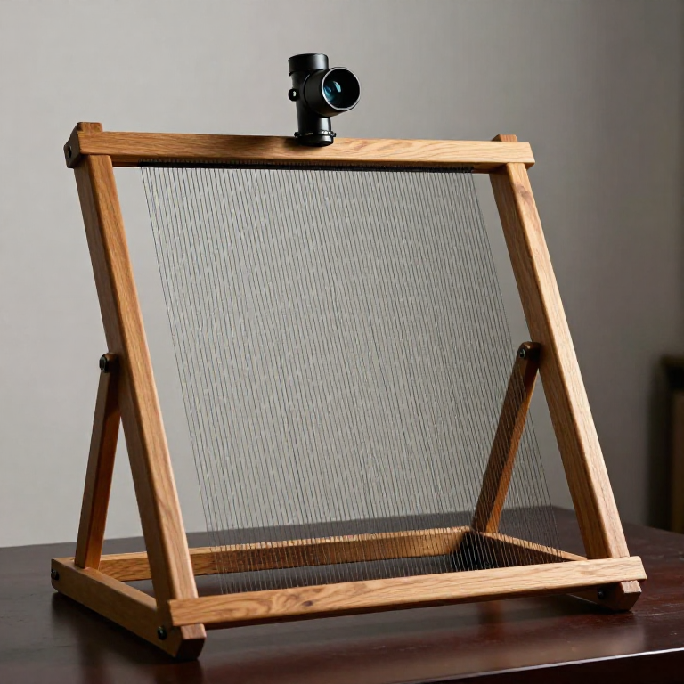


Perspective Frame
Medieval painters knew that distant things look smaller. What they did not have was a rule for how much smaller. Figures were sized by importance, buildings tipped at impossible angles, and floors ran uphill. Then in 1435 Leon Battista Alberti wrote down a construction that turned the problem into geometry.
His device makes the rule visible: a frame strung with a grid, held between the eye and the subject. Keep your eye at one fixed point, and every object in the world lands in a particular square. Copy square to square onto gridded paper and you have a correct projection — not an artistic judgement but a measurement.
This is a mathematics blueprint disguised as a drawing tool. What you build is a physical model of projection from a point.
Інструкції
Build a rigid open frame
Build a rigid open frame
Make a square wooden frame with a 300 mm opening. It must not flex — any movement of the frame changes the projection and ruins the whole method.
Матеріали для цього кроку:
 Дошка з твердої деревини1 штука
Необхідні інструменти ({count})
 Лінійка
Mark the frame every 30 mm on all four sides
Mark the frame every 30 mm on all four sides
Divide each side into ten equal parts and mark them. Accuracy here is the accuracy of every drawing you will make with it.
String a 10 × 10 grid across the opening
String a 10 × 10 grid across the opening
Run fine black thread between opposite marks, horizontal and vertical, and tension each one. Alberti called this the velo, the veil.
Матеріали для цього кроку:
 Бавовняна нитка10 метрів
Number the squares along two edges
Number the squares along two edges
Letter the columns and number the rows. You will be calling out coordinates constantly, and unlabelled squares get miscounted.
Build a fixed eyepiece on a stand
Build a fixed eyepiece on a stand
Mount a small sighting hole on an upright, facing the centre of the frame, about 400 mm back. This is the most important part of the whole device.
Fix the distance between eyepiece and frame
Fix the distance between eyepiece and frame
Lock the spacing and never change it mid-drawing. The projection is defined by a single viewpoint — move the eye and every square now shows something different.
Rule the same grid on your paper
Rule the same grid on your paper
Draw a 10 × 10 grid on paper in light pencil, with the same labels. It can be any size — half or double — and the drawing simply comes out scaled.
Матеріали для цього кроку:
 Набір кольорового картону1 пакет
Place a subject beyond the frame
Place a subject beyond the frame
Set up something with clear straight edges — a chair, a box, a tiled board. Rectilinear objects show perspective errors immediately; a rounded object hides them.
Sight through the eyepiece with one eye
Sight through the eyepiece with one eye
Close the other eye. Two eyes give two viewpoints and therefore two projections, and the grid readings will not settle.
Copy square by square, not line by line
Copy square by square, not line by line
Work one square at a time: note where an edge enters and leaves that square, and draw only that fragment. Resist drawing the object — draw the squares.
Mark where each straight edge crosses a thread
Mark where each straight edge crosses a thread
Record the crossing points and join them afterwards. A straight edge in the world stays straight in the projection, so two crossings define it completely.
Extend the receding edges and find where they meet
Extend the receding edges and find where they meet
Rule the parallel edges of the subject out beyond the drawing. They converge on a single point — the vanishing point — which you discovered rather than assumed.
Check the horizon sits at eye height
Check the horizon sits at eye height
Measure the height of the vanishing point in the drawing and compare with the eyepiece height. They should agree. This is the geometric meaning of the horizon line.
Move the eyepiece and redraw the same subject
Move the eyepiece and redraw the same subject
Shift the viewpoint sideways or in height and repeat. The vanishing point moves with it. That comparison is the experiment — perspective is a property of the viewpoint, not of the object.
Compendium — the geometry behind the picture
Compendium — the geometry behind the picture
What Alberti actually wrote. Della pittura (1435, dedicated in its Italian version to Brunelleschi) sets out the costruzione legittima: treat the picture as a window, place the eye at a fixed distance, and construct the diminishing floor tiles by geometry rather than by eye. The velo — the gridded veil — is the practical instrument for the same idea, and Dürer's well-known woodcuts of draughtsmen using gridded screens show it in use decades later.
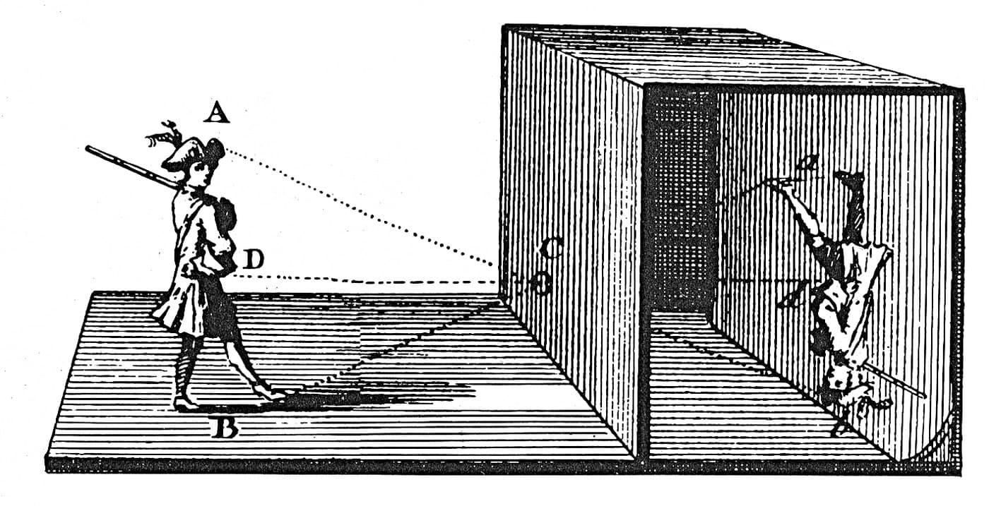
The mathematics you are physically modelling. Each thread crossing is a ray from the eye through the picture plane to a point in the world, so the frame performs a central projection from a point. This is projective geometry, and it has properties Euclidean geometry does not: straight lines stay straight, but parallel lines meet, and length and angle are not preserved. The vanishing point is the image of the point at infinity in that direction — a real construction of an idea that took mathematicians another two centuries to formalise, and which eventually produced the projective plane.
Why one eye, and why fixed. A projection needs a single centre. Two eyes produce two centres, which is exactly why we perceive depth — and exactly why binocular vision cannot be flattened onto one canvas. Every perspective painting is therefore addressed to a one-eyed viewer standing at a specific spot, and looks subtly wrong from anywhere else. Renaissance painters knew this and chose the viewpoint deliberately.
An honest correction. Brunelleschi is usually credited with demonstrating linear perspective around 1413-1425, with his famous mirror panel of the Florence Baptistery — but that panel is lost and his own writings on it do not survive. Alberti is the first to write it down. The two are often conflated into one origin story; the accurate version is that Brunelleschi demonstrated it and Alberti made it teachable. Nor was perspective invented from nothing: Euclid's Optics and the work of Alhazen (Ibn al-Haytham) supplied the underlying geometry of vision that both men were building on.
Матеріали
3- 1 штукаЗаповнювач
- 10 метрівЗаповнювач
- 1 пакетЗаповнювач
Пов'язані креслення
Ці креслення діляться знаннями — техніки, матеріали або принципи


CC0 Суспільне надбання
Це креслення випущено під ліцензією CC0. Ви можете вільно копіювати, змінювати, поширювати та використовувати цю роботу для будь-яких цілей без запиту дозволу.
Підтримайте мейкера, купуючи продукти через його креслення, де він отримує Комісію мейкера встановлену вендорами, або створіть нову ітерацію цього креслення та включіть його як зв'язок у власне креслення для розподілу доходу.