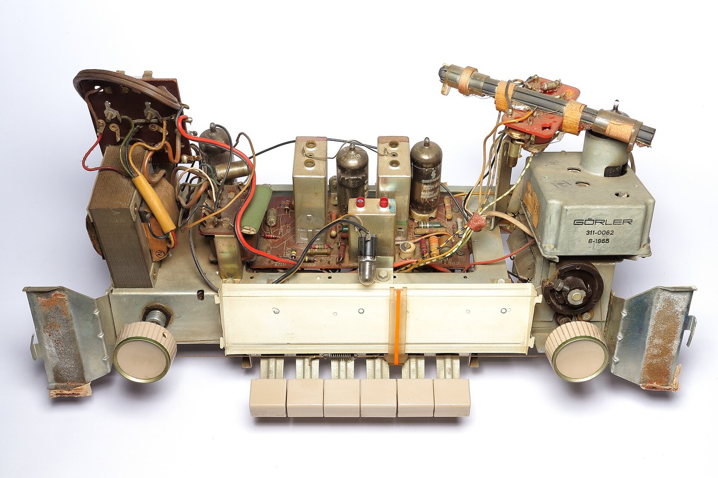


The Superheterodyne Receiver
Інструкції
Prove that mixing makes sum and difference frequencies
Prove that mixing makes sum and difference frequencies
The entire architecture rests on one property of a nonlinear device. Demonstrate it first.
- Feed two signal generators at different frequencies — say 1000 kHz and 1455 kHz — into a single diode or transistor mixer.
- Look at the output on a spectrum analyser.
- Identify every frequency present.
You will find the two originals, their sum, their difference, and a family of weaker products. The difference here is 455 kHz — the classic intermediate frequency of AM broadcast receivers.
The crucial detail is that a LINEAR device cannot do this. Add two sine waves in a linear circuit and you get exactly those two sine waves. New frequencies only appear when the device’s output is not proportional to its input — in a squaring nonlinearity, the cross-term between two inputs IS the sum-and-difference pair. Mixing is not addition; it is multiplication, and nonlinearity is what supplies it.
This is why a mixer is deliberately biased into its most curved region, when every other amplifier in the set is carefully biased to be as straight as possible. The same property that is distortion everywhere else is the entire function here.Матеріали для цього кроку:
 Germanium Diode (1N34A)4 штук
 Resistor Kit1 набір
 Capacitor Kit1 набір
 Perfboard / Protoboard1 штука
 Solder Wire (63/37 Rosin Core)1 reel
Необхідні інструменти ({count})
 Signal Generator
 Function Generator 10MHz
 Spectrum Analyser / FFT Software
 Oscilloscope 2-Channel 100MHz
 Digital Multimeter (Lab Grade)
 Soldering Station
 Clear Safety Glasses
Build the IF strip first, and make it excellent
Build the IF strip first, and make it excellent
Build the fixed-frequency amplifier before anything else, because it is the part that justifies the whole design.
- Wind two or three IF transformers tuned to 455 kHz — coupled pairs of tuned windings on ferrite formers.
- Build a two-stage amplifier with these as interstage coupling.
- Sweep it and plot the overall response.
- Adjust the coupling between each transformer’s primary and secondary and watch the shape of the response change.
As coupling increases the single peak flattens, then splits into a double hump. Critical coupling — just before the split — gives the flat top and steep sides that an ideal channel filter wants: everything inside the channel treated equally, everything outside rejected hard. A single tuned circuit can never do this; two coupled ones can.
This is the payoff of the whole architecture. Because this amplifier only ever works at 455 kHz, you can lavish effort on it — several coupled circuits, careful alignment, high gain — and that effort benefits every station, forever, without re-tuning.
Reverse-engineering note: the little screw-adjustable slugs in the top of each IF can are what set this alignment, and aligning a receiver means adjusting them in sequence against a signal generator. A misaligned IF strip is the most common reason an old radio sounds deaf or muffled.Матеріали для цього кроку:
 Enamelled Copper Wire20 m
 Ferrite Toroid Core4 штук
 IF Transformer Can (455 kHz)3 штукCapacitor Kit1 набірResistor Kit1 набір
Необхідні інструменти ({count})
Signal GeneratorOscilloscope 2-Channel 100MHzSpectrum Analyser / FFT Software LCR Meter (Benchtop)Soldering Station
 Digital Caliper 6-InchClear Safety Glasses
Add the local oscillator and make it track
Add the local oscillator and make it track
The oscillator must stay exactly one IF away from the wanted station across the whole band, which is harder than it sounds.
- Build a tunable oscillator using the second section of a ganged variable capacitor.
- Set it to run 455 kHz ABOVE the station frequency at the bottom of the band, and check the difference at the top of the band.
- Note the tracking error.
- Add a small series padder capacitor and a parallel trimmer, and re-check at bottom, middle and top.
Without correction the oscillator does not stay 455 kHz away — the difference drifts across the band, and the receiver goes deaf at one end. The reason is geometric: the signal circuit must cover a 3:1 frequency range while the oscillator covers a smaller ratio, and identical capacitor sections cannot do both.
The padder and trimmer are the fix, and they are why alignment has a defined procedure: set the trimmer at the high end, the padder at the low end, and repeat, because each interacts with the other.
Choosing the oscillator ABOVE the signal rather than below is deliberate and worth understanding — it makes the required tuning ratio smaller and therefore the tracking problem easier. That single choice is why almost every AM receiver ever built uses high-side injection.Матеріали для цього кроку:
 Variable Capacitor (Air Dielectric)1 штукаEnamelled Copper Wire10 mCapacitor Kit1 набір
 Trimmer Capacitor Set1 набір
Необхідні інструменти ({count})
Signal GeneratorSpectrum Analyser / FFT SoftwareOscilloscope 2-Channel 100MHz Grid-Dip OscillatorLCR Meter (Benchtop)Soldering StationClear Safety Glasses
Find the image, the flaw that comes free with the architecture
Find the image, the flaw that comes free with the architecture
Every superheterodyne has a second frequency it receives whether you want it or not. Find yours.
- Tune the receiver to a station at, say, 1000 kHz, with the oscillator at 1455 kHz.
- Now inject a test signal at 1910 kHz and watch the IF output.
- It comes through just as strongly.
Both 1000 kHz and 1910 kHz differ from the oscillator by exactly 455 kHz, so the mixer converts both to the IF and the amplifier cannot tell them apart. The unwanted one is the image, and it sits twice the IF away from the wanted station.
Nothing after the mixer can ever remove it, because by then the two are identical. The only defence is a tuned circuit BEFORE the mixer — the RF stage — which need not be sharp enough to separate adjacent channels, only sharp enough to reject something 910 kHz away. That is a far easier filter to build, which is exactly why the architecture works.
The trade is visible in the choice of IF. A high IF pushes the image further away and makes it easy to reject, but a high-frequency IF amplifier is harder to make selective. A low IF gives beautiful selectivity and a close, troublesome image. 455 kHz is the compromise the industry settled on for AM broadcast, and double-conversion receivers — high first IF for image rejection, low second IF for selectivity — refuse the compromise by doing it twice.Матеріали для цього кроку:
Enamelled Copper Wire10 mVariable Capacitor (Air Dielectric)1 штукаCapacitor Kit1 набір Graph Paper1 pad
Необхідні інструменти ({count})
Signal GeneratorSpectrum Analyser / FFT SoftwareOscilloscope 2-Channel 100MHzDigital Multimeter (Lab Grade)Clear Safety GlassesDetect, and close an automatic gain loop
Detect, and close an automatic gain loop
Add the last stage and one more feedback loop, this one deliberately slow.
- Follow the IF strip with a diode detector and audio filter to recover the modulation.
- Take the DC level from the detector — which is proportional to signal strength — and feed it back as a bias to the IF amplifier stages, arranged so a stronger signal REDUCES gain.
- Set the time constant to around 0.1 second.
- Tune across strong and weak stations and compare output levels with the loop connected and disconnected.
With automatic gain control the loud and quiet stations arrive at similar volume; without it, tuning across the band is painful. The loop measures its own output and corrects its own gain — negative feedback, the exact opposite sign to the regeneration in the previous blueprint, and used here for stability rather than gain.
The time constant is the whole design. Too fast and it fights the audio modulation itself, flattening the programme. Too slow and it cannot follow fading. A tenth of a second is slow compared with speech and fast compared with a signal fading — the loop is deliberately built to be blind to what you want to keep.
That principle recurs everywhere feedback is used: an automatic correction must be tuned to respond to the disturbance and ignore the signal. Get the separation wrong and the corrector eats the thing it was protecting.Матеріали для цього кроку:
Germanium Diode (1N34A)2 штукResistor Kit1 набірCapacitor Kit1 набір Crystal Earpiece (High Impedance)1 штука
Необхідні інструменти ({count})
Oscilloscope 2-Channel 100MHzSignal GeneratorDigital Multimeter (Lab Grade)Spectrum Analyser / FFT SoftwareSoldering Station Adjustable Bench Power Supply (30V/5A)Clear Safety Glasses
Матеріали
12- 6 штукЗаповнювач
- від$5.69
- 1 набірЗаповнювач
- 1 штукаЗаповнювач
- Заповнювач
- Заповнювач
- 4 штукЗаповнювач
- Заповнювач
- Заповнювач
- 1 набірЗаповнювач
- 1 padЗаповнювач
- Заповнювач
Необхідні інструменти
11- Заповнювач
- Заповнювач
- Заповнювач
- Заповнювач
- Заповнювач
- Заповнювач
- Заповнювач
- Заповнювач
- Заповнювач
- Заповнювач
Пов'язані креслення
Ці креслення діляться знаннями — техніки, матеріали або принципи


CC0 Суспільне надбання
Це креслення випущено під ліцензією CC0. Ви можете вільно копіювати, змінювати, поширювати та використовувати цю роботу для будь-яких цілей без запиту дозволу.
Підтримайте мейкера, купуючи продукти через його креслення, де він отримує Комісію мейкера встановлену вендорами, або створіть нову ітерацію цього креслення та включіть його як зв'язок у власне креслення для розподілу доходу.