МИСТЕЦТВО
КРАСА ТА ЗДОРОВ'Я
РЕМЕСЛО
КУЛЬТУРА ТА ІСТОРІЯ
РОЗВАГИ
СЕРЕДОВИЩЕ
ЇЖА ТА НАПІЇ
ЗБОРНА ІНЖЕНЕРІЯ
НАУК
СПОРТ
ТЕХНОЛОГІЯ
НОСИМО
Youblob (generated from this blueprint's notebook) · CC0


The Time-Delay Relay: Switching a Set Time Later
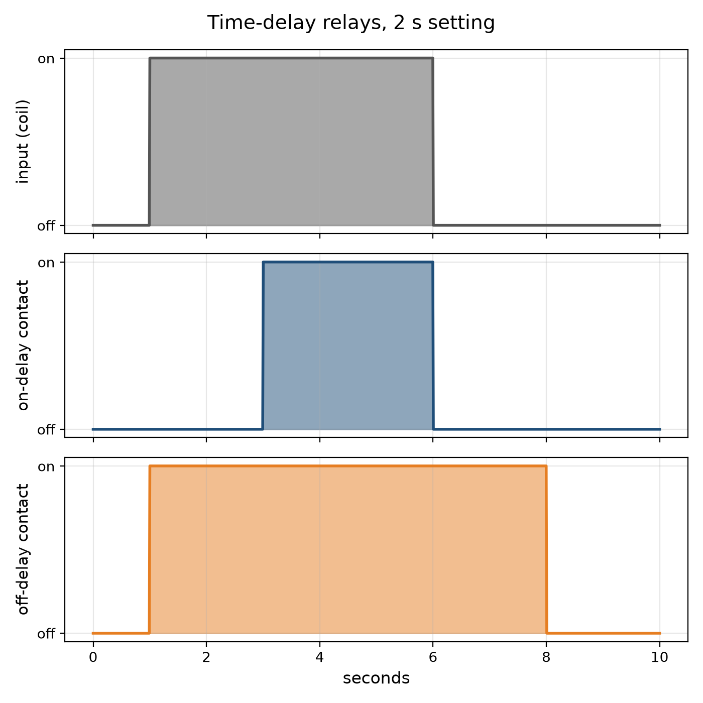
Many control jobs need a pause: start the motor, wait until it is up to speed, then load it; stop the burner, then run the fan a little longer to clear the heat; light the stairway, and switch it off a few minutes later. The time-delay relay does it. An on-delay closes its contact a set time after it is energised; an off-delay keeps its contact closed a set time after it is de-energised.
The earliest timed their delay with a dashpot — a piston pushing air or oil through a small adjustable hole — or with a bimetal warmed by a heater. Electronic relays charge a capacitor through a resistor and switch when it reaches a threshold.
This rung works out an RC delay and why capacitor tolerance and leakage limit it, draws on- and off-delay timing, and builds an on-delay relay with a 555 timer.
Початківець
About 3 hours
Інструкції
1
1
The RC delay and its limits
The RC delay and its limits
Завантаження блокнота Jupyter…
2
2
Build a 555 on-delay relay
Build a 555 on-delay relay
On a breadboard wire a 555 as a monostable from a 9–12 V supply: pins 4 and 8 to the supply, pin 1 to 0 V, a resistor R from the supply to pins 6 and 7 joined, a capacitor C from pins 6 and 7 to 0 V, 10 nF from pin 5 to 0 V, and pin 2 (trigger) held high through 10 kΩ with a push button to 0 V.
Pin 3 goes high for 1.1 RC after the button is pressed. Drive an NPN transistor from pin 3 through 1 kΩ, with the relay coil between the supply and the collector and a diode across the coil, reversed, to catch the coil's kick. Wire an LED through the relay's contact.
Time the relay with a stopwatch for three values of R. Plot delay against R: a straight line whose slope is 1.1 C. Swap in a second capacitor of the same marked value and watch the delay change — its tolerance.
Матеріали для цього кроку:
 Таймер NE5551 штука
 Транзистор NPN1 штука
 Реле SPDT1 штука
 Діод1 штука
 Набір конденсаторів1 штука
 Набір резисторів1 штука
 Кнопка1 штука
 Світлодіод 5 мм1 штука
 Макетна плата1 штука
 З'єднувальні дроти1 штука
 Реле часу1 штука
Необхідні інструменти ({count})
 Джерело живлення постійного струму
 Мультиметр
 Секундомір
3
3
The relay it times
The relay it times
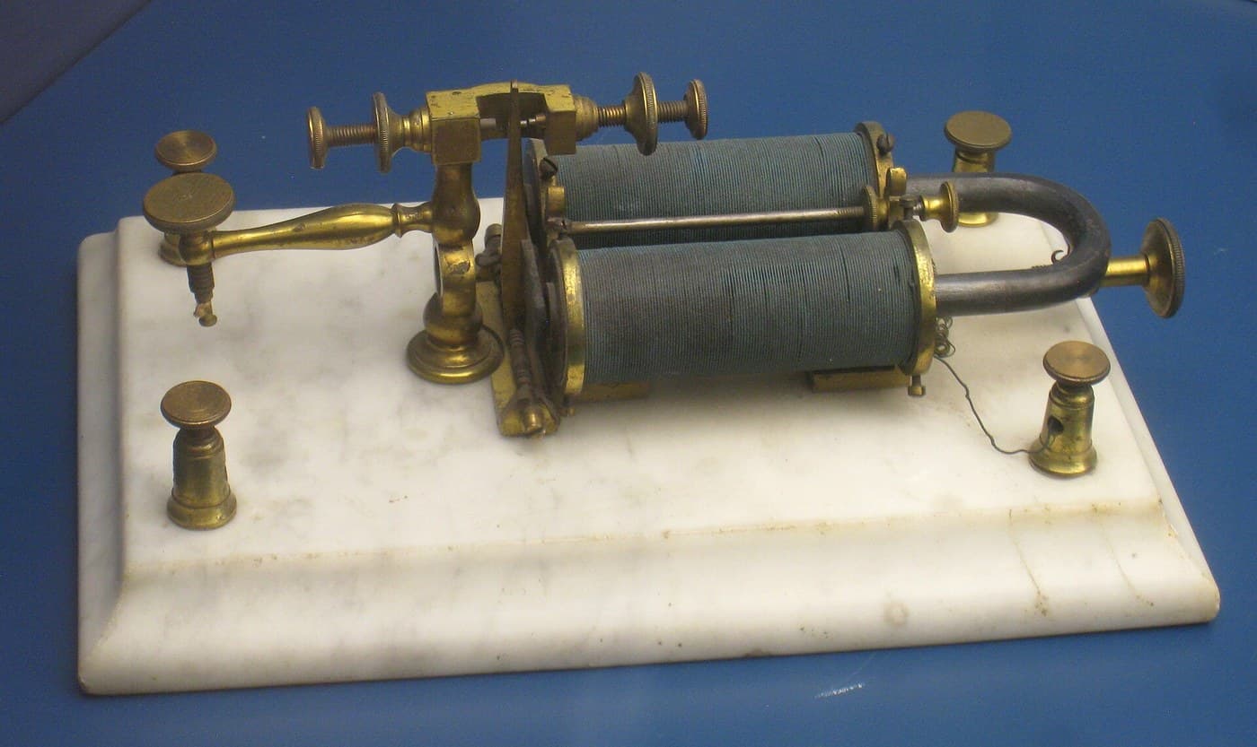
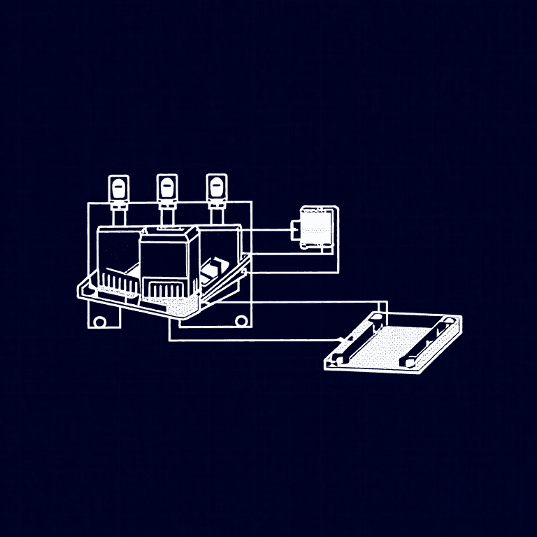
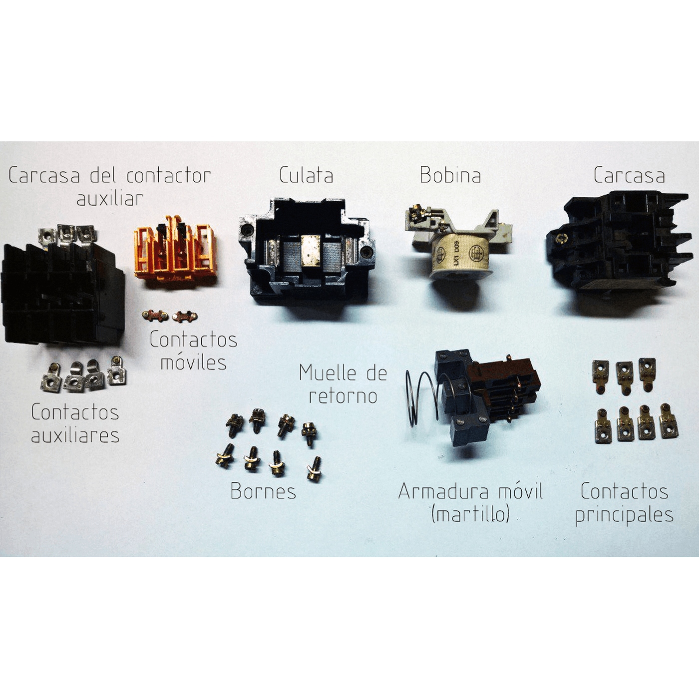
A time-delay relay is a relay with a clock in front of it. The embedded blueprint shows the electromagnetic relay it drives.
4
4
A timer that times wrong
A timer that times wrong
Time-delay relay faults.
Flow
Loading...
5
5
Context and honest limits
Context and honest limits
Pneumatic dashpot timers, thermal timers and motor-driven timers served machine and process control for decades; the 555 timer IC, introduced in 1972, made cheap electronic delays universal, and programmable controllers now provide timers in software.
**Honest limits.** An RC delay drifts with temperature and with the capacitor's age. For accurate long delays use a crystal-timed or counting timer. A relay switching mains loads must be wired and enclosed by someone qualified; the bench build stays at low voltage.
Матеріали
11- 1 штукаЗаповнювач
- 1 штукаЗаповнювач
- 1 штукаЗаповнювач
- 1 штукаЗаповнювач
- 1 штукаЗаповнювач
- від$5.64
- від$0.51
- від$3.54
- від$9.43
- від$1.60
- 1 штукаЗаповнювач
Необхідні інструменти
3- Заповнювач
- Заповнювач
- Заповнювач
Пов'язані креслення
Ці креслення діляться знаннями — техніки, матеріали або принципи


CC0 Суспільне надбання
Це креслення випущено під ліцензією CC0. Ви можете вільно копіювати, змінювати, поширювати та використовувати цю роботу для будь-яких цілей без запиту дозволу.
Підтримайте мейкера, купуючи продукти через його креслення, де він отримує Комісію мейкера встановлену вендорами, або створіть нову ітерацію цього креслення та включіть його як зв'язок у власне креслення для розподілу доходу.