ART
BEAUTY & WELLNESS
CRAFT
CULTURE & HISTORY
ENTERTAINMENT
ENVIRONMENT
FOOD & DRINKS
REVERSE ENGINEERING
SCIENCES
SPORTS
TECHNOLOGY
WEARABLES
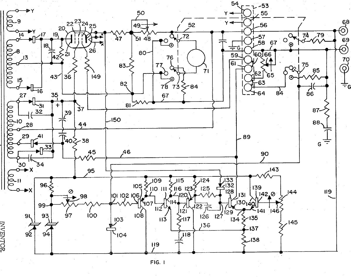


Bench Power Supply: Regulated, with Adjustable Current Limit and a Pentode Pass Tube (Gately, Forbro, US 3,243,690, 1966)
An adjustable bench supply that holds its output voltage steady and lets you set the most current it will deliver, so a circuit under test cannot be damaged. A pentode tube in series with the output is the regulator; a bridge with Zener references and a five-transistor amplifier keeps the output equal to the setting of one knob. A meter switch reads volts, amps, and the current limit, which can be set without disturbing the voltage.
Result: a regulated DC bench supply with adjustable current limiting.
Source: J. R. Gately (Forbro Design), US 3,243,690 (1966). Unknown: all component values and the output rating. Picture: the patent drawing.
Advanced
Unknown
Instructions
1
1
Wire the mains side
Wire the mains side
In a case, wire the power cord through a switch and a fuse to the primary of a transformer with four secondaries, and put a neon lamp across the primary to show the supply is on. One secondary (6.3 V) goes to two terminals for outside use, one heats the pentode, one is the main supply and one the bias supply. Ours: the case. Not given: the other winding voltages.
Materials for this step:
 Aluminium Enclosure Box1 case
 Flexible Cord with Plug1 piece
 Toggle Switch1 piece
 Fuse1 piece
 Step-Down Transformer1 four secondaries
 Neon Indicator Lamp1 piece
 Binding Post2 6.3 V terminals
Tools needed:
 Hand Drill
 Screwdriver Set
2
2
Build the rectifiers
Build the rectifiers
Rectify the centre-tapped main winding with two rectifiers and smooth it with a capacitor. From the bias winding make two more supplies: one through two rectifiers with by-pass capacitors to a smoothing capacitor, for the pentode's screen and the reference circuit; the other through one rectifier and a capacitor, for the pentode's grid bias. Not given: the values.
Materials for this step:
 Diode5 rectifiers
 Electrolytic Capacitor3 smoothing
 Capacitor Kit1 by-pass
 Solder Wire1 as needed
Tools needed:
 Soldering Iron
3
3
Fit the pass tube and reference
Fit the pass tube and reference
Put the pentode in series with the positive output: plate to the main supply, cathode through two current-sensing resistors (one fixed, one adjustable) to the + output terminal; suppressor tied to the cathode, screen fed through a resistor. Build the reference: a Zener fed through a resistor feeds a second Zener at constant current, giving a fixed voltage. Against it set two resistors and the voltage-control variable resistor: the output voltage is proportional to that resistor's setting. Not given: the tube type and values.
Materials for this step:
 Pentode Valve1 series pass tube
 Zener Diode2 pieces
 Resistor1 set
 Rheostat2 voltage control, current-limit rangeBinding Post2 output + and -Solder Wire1 as needed
Tools needed:
Soldering Iron4
4
Build the error amplifier and current limit
Build the error amplifier and current limit
Build a five-transistor amplifier that drives the pentode's grid to keep the bridge balanced: a PNP emitter follower, an NPN stage, a PNP emitter follower with a resistor-capacitor roll-off against oscillation, a PNP driver whose base resistor has a capacitor across it for quick response, and an NPN clamp whose base is set by a potentiometer. Feed the voltage across the current-sensing resistors to the driver's base through a diode: above the limit it takes over and turns the pentode down. Choose the fixed sensing resistor to limit at about 125 % of rated current, trim with the potentiometer, and use the adjustable one to set lower limits. Not given: the transistor types and values.
Materials for this step:
 PNP Transistor3 pieces
 NPN Transistor2 piecesDiode1 piece
 Potentiometer1 pieceCapacitor Kit1 roll-off, speed-upResistor1 setSolder Wire1 as needed
Tools needed:
Soldering Iron5
5
Fit the meter and use it
Fit the meter and use it
Fit a meter with a four-pole, three-position switch. Position 1 reads output volts through a multiplier resistor; position 2 reads current across a shunt in the negative line; position 3 (spring-return) puts a load resistor across the output and swaps a fixed resistor for the voltage control, so you can turn the limit control until the current limits at the value you want, without touching the voltage setting. Release the switch and use the supply.
Materials for this step:
 Moving-Coil Panel Meter1 piece
 Rotary Switch1 4-pole, 3-positionResistor1 multiplier, shunt, load resistors
 Unknown Material1 terminal strip
Tools needed:
Soldering IronScrewdriver SetMaterials
21- 1 casePlaceholder
- 1 piecePlaceholder
- Placeholder
- 1 piecePlaceholder
- 1 four secondariesPlaceholder
- 1 piecePlaceholder
- Placeholder
- 1 piecePlaceholder
- 3 smoothingPlaceholder
- 1 roll-off, speed-upPlaceholder
- 3 as neededPlaceholder
- 1 series pass tubePlaceholder
- 2 piecesPlaceholder
- 1 multiplier, shunt, load resistorsPlaceholder
- 2 voltage control, current-limit rangePlaceholder
- 3 piecesPlaceholder
- 2 piecesPlaceholder
- Placeholder
- 1 piecePlaceholder
- 1 4-pole, 3-positionPlaceholder
- 1 terminal stripPlaceholder
This blueprint makes

CC0 Public Domain
This blueprint is released under CC0. You are free to copy, modify, distribute, and use this work for any purpose, without asking permission.
Support the Maker by purchasing products through their Blueprint where they earn a Maker Commission set by Vendors, or create a new iteration of this Blueprint and include it as a connection in your own Blueprint to share revenue.