ART
BEAUTY & WELLNESS
CRAFT
CULTURE & HISTORY
ENTERTAINMENT
ENVIRONMENT
FOOD & DRINKS
REVERSE ENGINEERING
SCIENCES
SPORTS
TECHNOLOGY
WEARABLES
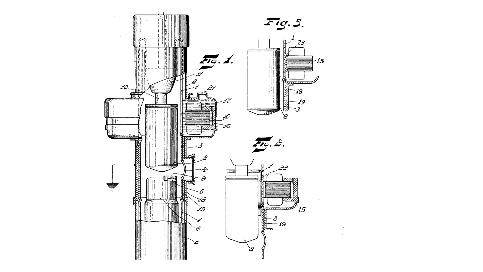


Bouwers Rotating-Anode X-Ray Tube
Coolidge's tube of 1913 solved the electrical problem: a heated filament sets the current, so the operator finally controls the beam instead of negotiating with a bag of gas. What it handed over was a **thermal** problem, and a brutal one.
Only about one per cent of the power you put into an X-ray tube leaves as X-rays. The rest becomes heat, delivered into a focal spot a couple of millimetres across. At 100 kV and 400 mA that is roughly 40 kilowatts arriving in an area smaller than a grain of rice - hundreds of times the power density of a hotplate, into tungsten. The spot does not gradually warm. It pits, and then it melts, and a pitted anode makes a blurred and asymmetric beam for the rest of the tube's life.
Albert Bouwers' answer at Philips was to stop letting the beam hit the same place twice. **US 1,933,005** "X-ray tube", filed 13. March 1930 and granted 31. October 1933: put the target on a disc and spin it, so the beam traces a ring of fresh metal instead of a point. The patent says why plainly - "since the bombarded surface of the anticathode is materially larger than in tubes of the type having a concentrated focal spot which is formed on a stationary anticathode, such tubes present the advantage that a much higher load may be applied". It sold as the Rotalix from 1929.
**The clever part is how it is driven.** You cannot run a shaft through the wall of a vacuum tube and still have a vacuum. So the anode is mounted on a rotor sealed INSIDE the envelope, and the patent claims "a metallic stator carrying magnetic coils for imparting rotative motion to said anode and arranged without the tube" - an induction motor whose stator is outside the glass and whose rotor is inside it, coupled by nothing but a magnetic field. Nothing passes through the wall at all.
**That is what you will build.** Not an X-ray tube - this blueprint asks nobody to make ionising radiation - but the actual mechanism Bouwers patented: a stator outside a sealed glass jar spinning a rotor inside it, with no connection between them. It is the same motor, at the same working principle, and you will measure its speed, its slip and its run-up time.
Intermediate
3 hours
Instructions
1
1
Wind a two-phase stator
Wind a two-phase stator
An induction motor needs a magnetic field that ROTATES. Two coils facing each other and driven together do not make one - they make a field that pulses back and forth along a line, which will rattle a rotor and never turn it. You need at least two pairs, at right angles, driven out of phase.
Wind four coils of about 300 turns of 0.4 mm enamelled copper wire on plastic formers roughly 25 mm across. Two coils opposite each other form one phase; the other two, at ninety degrees, form the second.
Mount all four around a ring of plywood or 3D-printed frame sized so the jar from step 2 drops through the middle with 3-5 mm clearance. The gap matters more than the turns: field strength falls off fast, and every extra millimetre of glass between stator and rotor costs you torque.
Bouwers had the same constraint and it is visible in the patent drawing - the envelope is made deliberately CYLINDRICAL and narrow where it passes through the stator, so the coils can sit as close to the rotor as the glass allows.
Materials for this step:
 Enamelled Copper Wire100 m
 Plywood Sheet1 piece
 PVA Wood Glue20 ml
Tools needed:
 Wire Strippers
 Soldering Station
 Digital Multimeter - Lab Grade
 Digital Caliper 6-Inch
 Craft Knife
2
2
The rotor, sealed inside, touching nothing outside
The rotor, sealed inside, touching nothing outside
The rotor must be electrically CONDUCTIVE and does not need to be magnetic. The rotating field induces eddy currents in it, those currents make their own field, and the two fields drag the rotor round. Aluminium is ideal, copper works, steel works poorly, and plastic does nothing at all.
Turn or cut a solid aluminium cylinder about 20 mm across and 40 mm long. Drill it centrally at each end and press in two short steel stub axles, or simply glue in the inner races of two small ball bearings.
Build a light frame inside a straight-sided glass jar to carry the bearings so the rotor spins freely on the jar's axis. Then close the jar. From this point nothing electrical crosses the wall - which is the entire point of the exercise.
If you have the means to pull even a rough vacuum on the jar, do it and note how much longer the rotor coasts. Bouwers' rotor ran in a hard vacuum with no air drag at all, and also with no air to carry heat away from the bearings, which is the trade the compendium comes back to.
Materials for this step:
 Aluminium Rod1 piece
 Ball Bearing2 pieces
 Glass Jar1 piece
 Acrylic Sheet1 piece
Tools needed:
 Cordless Drill/Driver
 Drill Bit Index
 Hacksaw
 File SetDigital Caliper 6-Inch
3
3
Make the field rotate, and prove it does
Make the field rotate, and prove it does
Drive phase A from a function generator through a small audio power amplifier - a sine at 40-60 Hz, a few volts. Mains is not needed anywhere in this build and should not be used. Drive phase B from the SAME amplifier output through a capacitor, which shifts its current in time relative to phase A.
Driving it from a generator rather than a transformer is worth the extra part: you can sweep the frequency and watch the rotor follow it, which turns step 4 from one measurement into a curve.
That phase shift is the whole trick. With A at its peak while B is at zero, and B peaking a quarter cycle later, the combined field points in a direction that walks around the ring at supply frequency. Start with 4-10 microfarads, non-polarised, rated well above your supply voltage.
**Prove the field rotates before you blame the rotor.** Put a small compass in the middle of the stator with the power on at low voltage: it should spin or hunt continuously rather than settle. If it settles and quivers, you have a pulsing field and the capacitor value or wiring is wrong.
Then drop the jar into the ring and power up. The rotor should start on its own. If it only spins when you help it by hand, the phase shift is present but too small - try a different capacitor.
Materials for this step:
 Capacitor Kit1 piece
Tools needed:
 Function Generator
 Class-D Audio Amplifier BoardDigital Multimeter - Lab Grade
 Compass
 Alligator Clip Test Leads
 Safety Goggles
4
4
Measure speed, slip and run-up
Measure speed, slip and run-up
**Speed.** Mark one line on the rotor with a marker and read it with an optical tachometer, or film it at a known frame rate and count. A two-pole field at 50 Hz rotates at 3000 rpm; at 60 Hz, 3600.
**Slip.** Your rotor will always turn slower than the field, and that is not a fault - it is how the machine works. Eddy currents are only induced when the field moves RELATIVE to the rotor, so a rotor turning at exactly field speed would have no induced current and no torque at all. Measure the difference as a percentage of field speed. A few per cent unloaded is normal; it grows the moment you load it.
**Run-up.** Time it from switch-on to steady speed. Then think about what that means clinically: a real tube must be at full speed BEFORE the exposure starts, or the spot sits on one patch of a barely-moving disc and you have gained nothing. The whine you hear in an X-ray room a second before the click is exactly this.
**Coast-down.** Cut the power and time how long it takes to stop. That number is your bearing quality and your air drag, and it is the number that decides whether a real tube lasts five years or fails in one.
Tools needed:
 Digital Tachometer
 StopwatchDigital Multimeter - Lab Grade
5
5
The heat arithmetic that forced all this
The heat arithmetic that forced all this
Loading Jupyter Notebook...
6
6
When the rotor will not turn
When the rotor will not turn
Nearly every failure here is the field, not the rotor. Work down in order - the compass test in step 3 answers the first two questions directly.
Flow
Loading...
Tools needed:
CompassDigital Multimeter - Lab Grade7
7
Compendium: the bearing, and what a focal spot really is
Compendium: the bearing, and what a focal spot really is
**The bearing is the hard part.** It runs at 3,000 to 10,000 rpm, in a hard vacuum, a few centimetres from a disc that may be glowing. Ordinary lubricants evaporate instantly at that pressure and would poison the vacuum, so the balls run dry or in a thin metallic film - often lead or silver plated onto the races. That is why a rotating anode tube is expensive, why it is rated in exposures rather than hours, and why the failure is usually mechanical rather than electrical. Modern high-end tubes replace the balls with a liquid-metal spiral-groove bearing, which also conducts heat out of the anode - solving two problems with one part.
**The line-focus principle, which doubles the trick.** The target face is not perpendicular to the beam; it is bevelled, typically 12 to 17 degrees. The electrons land on a long, thin patch - lots of area, good for heat - but viewed from where the patient is, that patch is foreshortened into a near-square spot. You get a large heated area and a small apparent source at the same time. This is geometry doing thermal work, and it stacks with rotation rather than competing with it.
**Its cost is the heel effect.** Because the target is angled, X-rays leaving toward the anode side pass through more of the target itself and are absorbed. The beam is measurably weaker on the anode side of the field - which is why radiographers put the thicker part of the patient toward the cathode.
**Why nothing replaced it.** Ninety years on, essentially every diagnostic X-ray tube in the world is still a bevelled tungsten disc, spun by an induction motor through a sealed wall, exactly as this patent describes. The discs are bigger, the bearings are better, the envelopes are metal and ceramic rather than glass - and the drawing on this blueprint would still be recognised by anyone who services them.
Materials
8- Placeholder
- 1 piecePlaceholder
- 20 mlPlaceholder
- 1 piecePlaceholder
- Placeholder
- 1 piecePlaceholder
- 1 piecePlaceholder
- 1 piecePlaceholder
Tools Required
16- Placeholder
- Placeholder
- Placeholder
- Placeholder
- Placeholder
- 1 vendor sell this, none ship to you yetPlaceholder
- Placeholder
- Placeholder
- Placeholder
- Placeholder
- Placeholder
- Placeholder
- Placeholder
- Placeholder
- Placeholder
- Placeholder
Related Blueprints
These blueprints share knowledge with this one — techniques, materials, or principles that connect them in the learning graph.

CC0 Public Domain
This blueprint is released under CC0. You are free to copy, modify, distribute, and use this work for any purpose, without asking permission.
Support the Maker by purchasing products through their Blueprint where they earn a Maker Commission set by Vendors, or create a new iteration of this Blueprint and include it as a connection in your own Blueprint to share revenue.