
Collaboration
ART
BEAUTY & WELLNESS
CRAFT
CULTURE & HISTORY
ENTERTAINMENT
ENVIRONMENT
FOOD & DRINKS
REVERSE ENGINEERING
SCIENCES
SPORTS
TECHNOLOGY
WEARABLES
Homemade Wood Lathe: Hardwood Bed, Sliding Headstock and Tailstock, Steel Spindle With Stepped Pulley (Boy Mechanic, 1915)
Woody

Created by

Woody

13. November 2026NO
1
0
0
0
0

Homemade Wood Lathe: Hardwood Bed, Sliding Headstock and Tailstock, Steel Spindle With Stepped Pulley (Boy Mechanic, 1915)

E. E. Hulgan's lathe from The Boy Mechanic, Book 2 (1915), "in which wood and light metal articles may be turned": a 5 ft bed of two 2 by 4 in hardwood rails, a headstock clamped by bolts with a 3/4 in steel spindle in brass bearings and a three-step pulley, a bolted hardwood tailstock with a screw-fed dead centre, a sliding tool rest, and a screw-on chuck. Driven from a countershaft or by foot.
Advanced
About 1-2 weeks

Instructions

1

His sizes, and the pulley speeds

Loading Jupyter Notebook...
2

Read The Boy Mechanic, Book 2

"A strong, substantial lathe in which wood and light metal articles may be turned can be made by carefully following the description below and the detailed drawings of the parts."
3

Make the bed

Cut two pieces of straight-grained, smooth 2 by 4 in hardwood, 5 ft long, and hold them apart at each end with blocks of wood 2 in wide (Fig. 9 shows 2 in rails with a 2 in gap). The bed can be longer or shorter.

Materials for this step:

Hardwood BoardHardwood Board2 pieces
Wood ScrewsWood Screws1 piece

Tools needed:

Hand SawHand Saw
Hand PlaneHand Plane
Hand DrillHand Drill
Tape MeasureTape Measure
4

Build the headstock frame

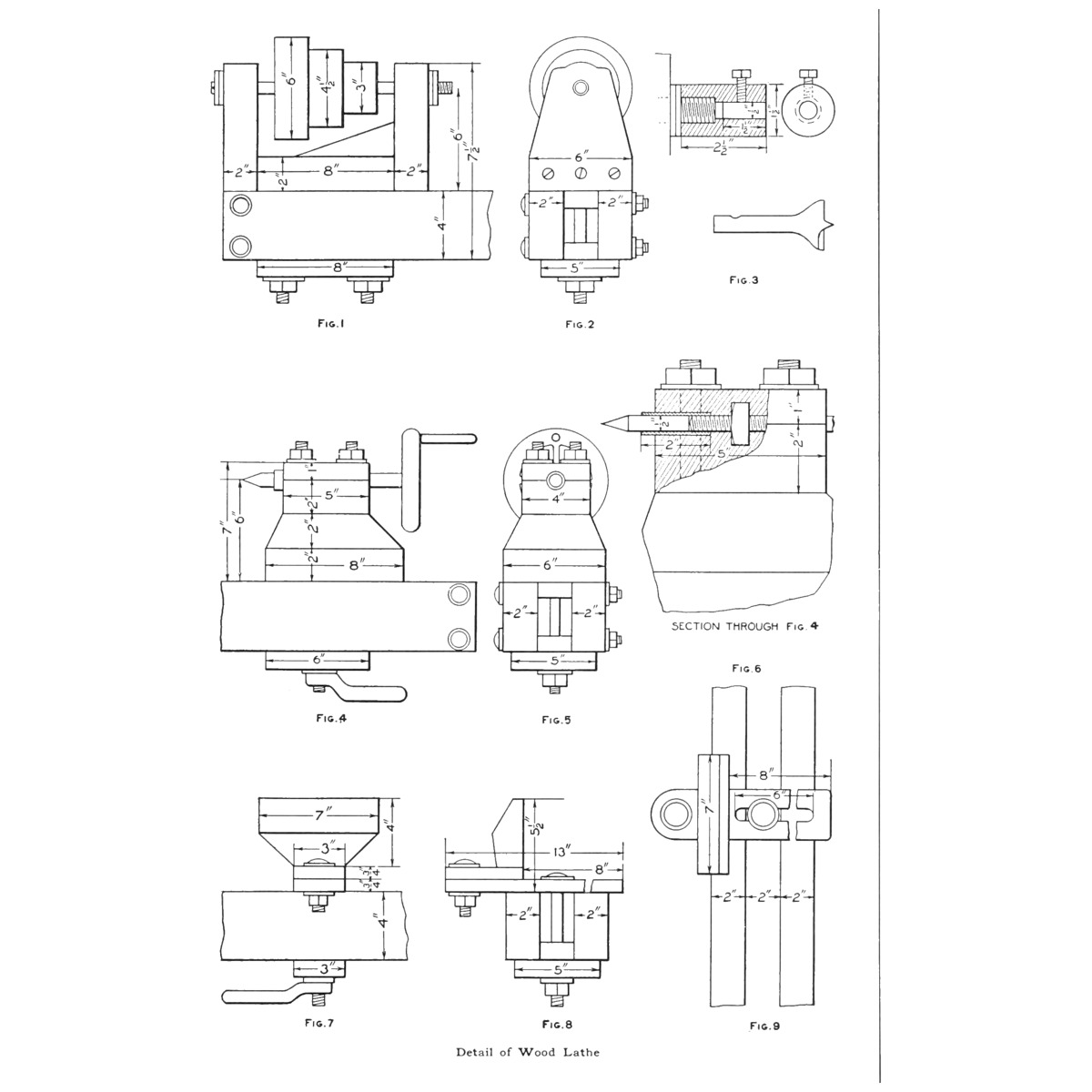
Make the two hardwood end pieces to the shape of Figs. 1 and 2 (2 in thick, 2 in apart on an 8 in base, 7-1/2 in high, 6 in wide at the bottom) and screw them to the base. Nail a slider 1 in thick and 10 in long, just wide enough to slide between the bed rails, under the base, 2 in from its rear end. Bore two 1/2 in holes through base and slider and put two 1/2 in bolts through them and through another slide and board under the bed, so tightening the nuts clamps the headstock. Screw a half-round wedge-shaped brace inside the frame against the front end.

Materials for this step:

Hardwood BoardHardwood Board1 piece
Carriage BoltCarriage Bolt2 pieces
Hex NutHex Nut2 pieces
Wood ScrewsWood Screws1 piece
NailsNails1 piece

Tools needed:

Hand SawHand Saw
ChiselsChisels
Brace and BitBrace and Bit
Hand DrillHand Drill
5

Make the spindle and bearings

Make the spindle of tool steel or steel tubing, 3/4 in in diameter and 14 in long, and cut a thread on one end. Rivet on a hardened steel collar, 1/4 by 1-1/2 in, to turn against another collar of the same size on the headstock; screw a third collar to the rear end piece and fix a collar with a removable pin on the spindle, fitted to turn easily with no end play. Drill brass tubing for the spindle as bearings and wedge them into the headstock 6 in above the bed, in line; drill small oil holes from the top.

Materials for this step:

Tool Steel BarTool Steel Bar1 piece
Steel TubingSteel Tubing1 piece
Shaft CollarShaft Collar4 pieces
Steel RivetsSteel Rivets1 piece
Brass TubeBrass Tube1 piece

Tools needed:

HacksawHacksaw
Tap and Die SetTap and Die Set
Hand DrillHand Drill
Files (Hand File)Files (Hand File)
Bench ViseBench Vise
HammerHammer
6

Fit the stepped pulley

Make the pulleys 2 in wide, with the diameters on the drawing: 6, 4-1/2 and 3 in. Fasten them to the spindle with a removable pin. (Turned hardwood is our choice of material; he does not say.)

Materials for this step:

Hardwood BoardHardwood Board1 piece

Tools needed:

Hand SawHand Saw
Brace and BitBrace and Bit
Hand DrillHand Drill
7

Make the chuck and centres

For the chuck (Fig. 3), take shafting 1-1/2 in in diameter and 2-1/2 in long, drill a 1/2 in hole through its centre, ream and thread one end to fit the spindle, and fit a setscrew over the 1/2 in hole. Make a wood-turning centre, and other centres and drills, from 1/2 in tool steel.

Materials for this step:

Mild Steel Round BarMild Steel Round Bar1 piece
Tool Steel BarTool Steel Bar1 piece
Cup Point Set ScrewCup Point Set Screw1 piece

Tools needed:

HacksawHacksaw
Hand DrillHand Drill
ReamerReamer
Tap and Die SetTap and Die Set
Files (Hand File)Files (Hand File)
Bench ViseBench Vise
8

Build the tailstock

Build the tailstock (Figs. 4-6) of three pieces of hardwood 2 in thick and one 1 in thick, shaped as drawn, held together with four bolts 7-1/2 in long. Give it sliders and clamp it to the bed like the headstock, but with one bolt, and weld a handle to its nut for easy clamping. Drill a piece of tubing 2 in long for a 1/2 in dead centre and set it 1-1/2 in into the joint between the two upper pieces. Bore for a 1/2 in bolt to slide in the tube; chisel a recess behind the tube for a 1/2 in nut; turn a bolt 7 in long, threaded for 2 in, into nut and tube, and rivet a handle or wheel on its end. Make the centre of 1/2 in tool steel with a tapered point.

Materials for this step:

Hardwood BoardHardwood Board2 pieces
Carriage BoltCarriage Bolt5 pieces
Hex NutHex Nut2 pieces
Steel TubingSteel Tubing1 piece
Tool Steel BarTool Steel Bar1 piece
Steel RivetsSteel Rivets1 piece

Tools needed:

Hand SawHand Saw
ChiselsChisels
Brace and BitBrace and Bit
Hand DrillHand Drill
Coal ForgeCoal Forge
AnvilAnvil
Blacksmith HammerBlacksmith Hammer
Files (Hand File)Files (Hand File)
9

Make the tool rest

The tool rest (Figs. 7-9) has a slide 3/4 by 3 by 13 in with a slot 1/2 by 6 in. Bolt the rest base on the slide so it can be adjusted, and screw the rest to the base. Raise or lower it with wedges between slide and base, and clamp it to the bed like the tailstock.

Materials for this step:

Hardwood BoardHardwood Board1 piece
Carriage BoltCarriage Bolt1 piece
Hex NutHex Nut1 piece
Wood ScrewsWood Screws1 piece

Tools needed:

Hand SawHand Saw
ChiselsChisels
Brace and BitBrace and Bit
10

Troubleshooting

Wood lathe troubleshooting.

Flow

Loading...
11

History and honest limits

From "How to Make a Wood Lathe" by E. E. Hulgan, Marion, Ind., in **The Boy Mechanic, Book 2**, Popular Mechanics, 1915 (Project Gutenberg 44585; checked on the archive.org scan boymechanicbook200chic2, pp. 434-436). Part shapes come from his Figs. 1-9; he gives no pulley material and no countershaft or foot-drive details. The pulley material, tools and metric figures are ours.

Materials

12

Tools Required

15

This blueprint makes

Related Blueprints

These blueprints share knowledge with this one โ€” techniques, materials, or principles that connect them in the learning graph.
CC0 Public Domain

This blueprint is released under CC0. You are free to copy, modify, distribute, and use this work for any purpose, without asking permission.

Support the Maker by purchasing products through their Blueprint where they earn a Maker Commission set by Vendors, or create a new iteration of this Blueprint and include it as a connection in your own Blueprint to share revenue.

Discussion

(0)

Log in to join the discussion

Loading comments...