Collaboration
ART
BEAUTY & WELLNESS
CRAFT
CULTURE & HISTORY
ENTERTAINMENT
ENVIRONMENT
FOOD & DRINKS
REVERSE ENGINEERING
SCIENCES
SPORTS
TECHNOLOGY
WEARABLES
Hinged-Float Double-Dasher Churn: Floats That Close Going Down and Fall Open Coming Up
Buttercup

Created by

Buttercup

10. November 2026IE
0
0
0
0
0

Hinged-Float Double-Dasher Churn: Floats That Close Going Down and Fall Open Coming Up

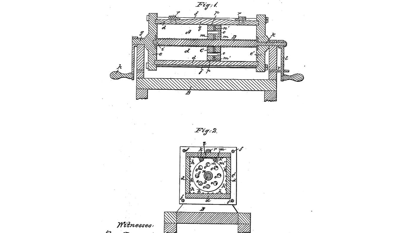
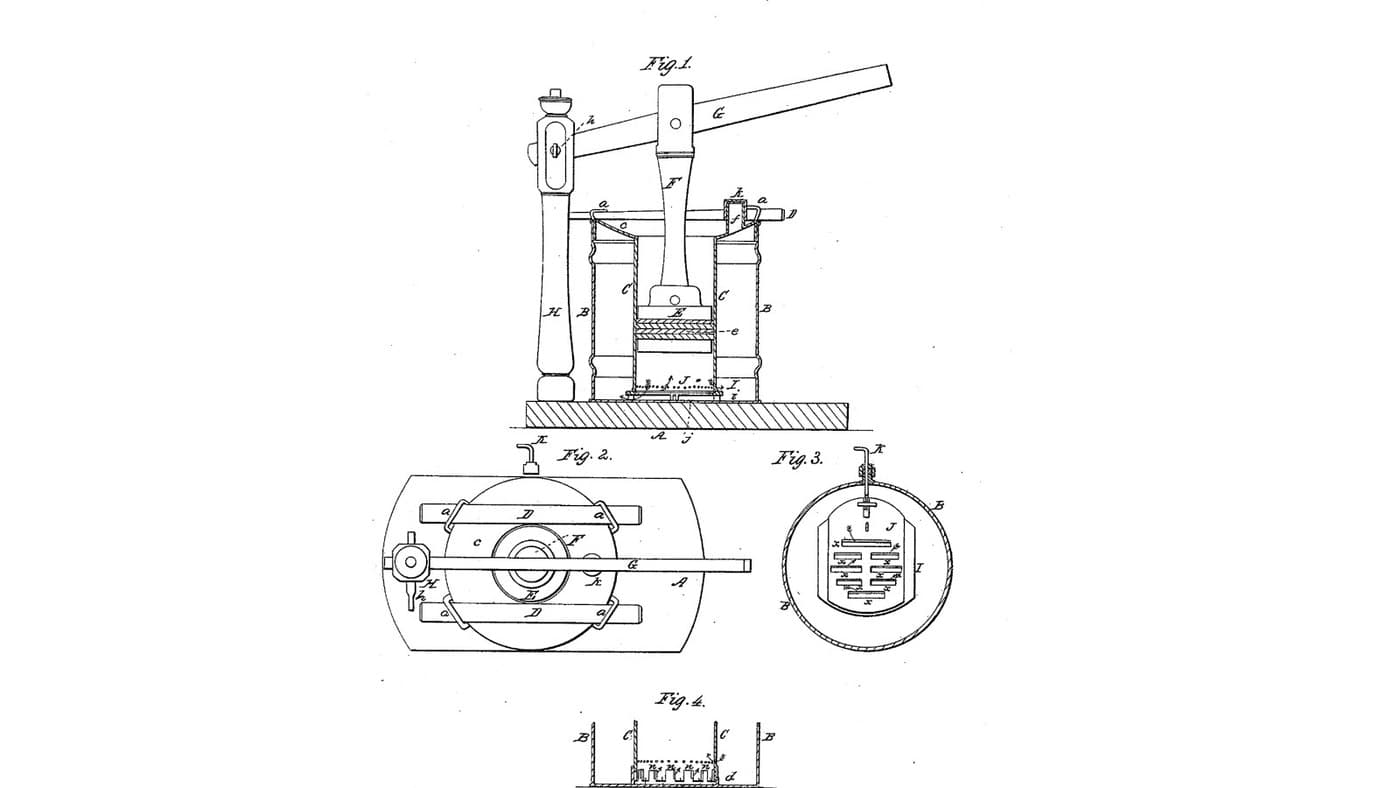
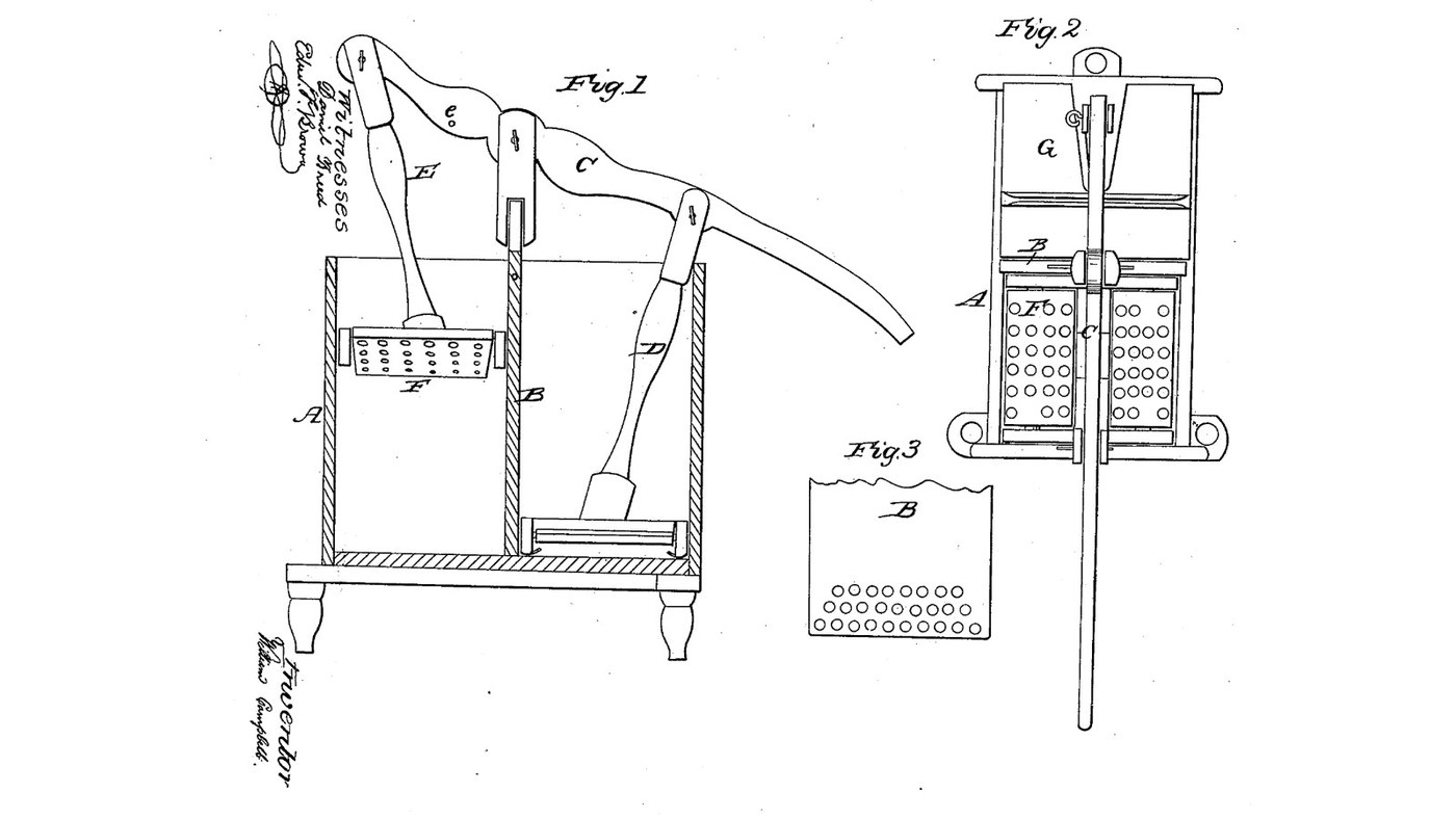
William Campbell of Waterloo, Pennsylvania, received US 25,383, dated 13 September 1859, for a dasher head made of perforated floats hinged in a frame. A lever on top of a removable partition works two dashers, one in each half of a box; as one goes down the other comes up. Going down, the cream presses the floats shut and the head fills the box's end; coming up, they fall open so the cream does not spatter over the top. Moving one shaft nearer the pivot shortens its stroke, and the butter gathers round it. Campbell gives no sizes; every size here is ours.
Intermediate
About 2 days

Instructions

1

Long stroke, short stroke

Loading Jupyter Notebook...
2

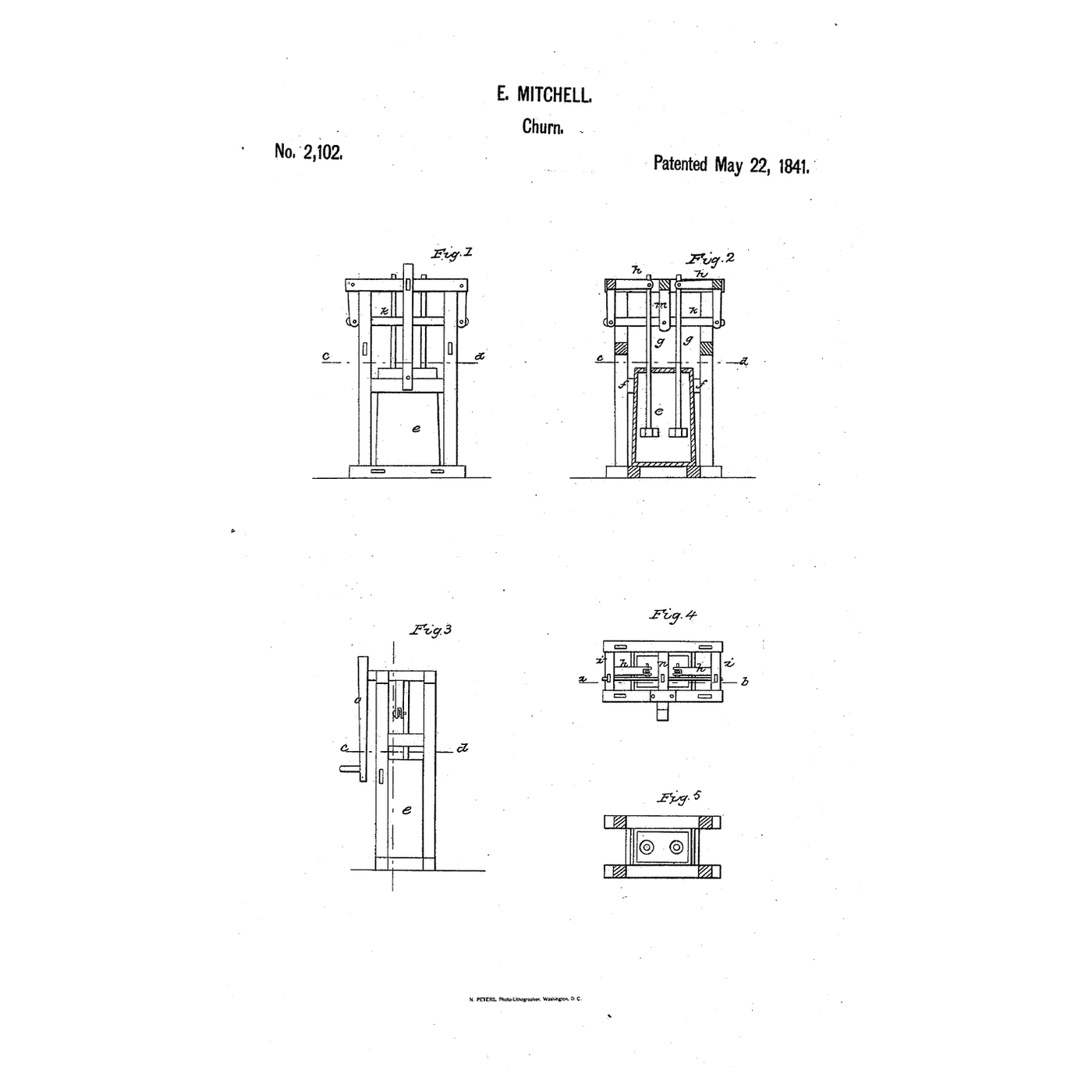
A lever working two dashers, before it

Campbell knew a lever with two dashers was not new. What he added were the hinged, perforated floats.
3

Read US 25,383

"The descending dasher has its floats F, closed by the resistance of the cream. As the dasher head fills the end of the box, the cream is partly driven downward into the opposite end of the churn. Some of the milk rises through the perforations in the descending dasher; then upon the return stroke of lever C the milk takes the opposite course."
4

Box A with legs

From 20 mm hardwood cut a bottom 540 x 290 mm, two sides 540 x 400 mm and two ends 250 x 400 mm. In each side's inner face, in the middle, cut a groove 19 mm wide and 6 mm deep from top to bottom for the partition. Glue and screw the ends between the sides and the box onto the bottom. Drill an 18 mm hole low in each end for the buttermilk and shape two tapered hardwood plugs to fit. Screw four legs of 70 mm timber, 300 mm long, under the corners. Fill the box with water overnight so it swells tight, then empty it.

Materials for this step:

Hardwood BoardHardwood Board3 pieces
Softwood Timber 70x70mmSoftwood Timber 70x70mm1 piece
Hardwood DowelsHardwood Dowels1 piece
Wood GlueWood Glue1 piece
Wood ScrewsWood Screws30 pieces

Tools needed:

Table SawTable Saw
Hand SawHand Saw
ChiselsChisels
Cordless DrillCordless Drill
Spade Bit SetSpade Bit Set
Bar ClampBar Clamp
Try SquareTry Square
Tape MeasureTape Measure
WaterWater
5

Partition B

Cut an 18 mm hardwood partition 261 x 400 mm to slide down the grooves, with a post 60 mm wide rising 170 mm above it. Drill four rows of six 16 mm holes across its lower end, as Fig. 3 draws, the lowest row 25 mm up. Saw a 24 mm slot 50 mm deep in the top of the post and bore a 12.6 mm hole across it 150 mm above the box for the lever's pin.

Materials for this step:

Hardwood BoardHardwood Board1 piece

Tools needed:

Hand SawHand Saw
JigsawJigsaw
Cordless DrillCordless Drill
Spade Bit SetSpade Bit Set
Drill Bit SetDrill Bit Set
ChiselsChisels
6

Dasher heads with hinged floats F

For each head make a hardwood frame 230 x 230 mm of 12 mm strips with a 12 mm bar across the middle and a block on top of the bar for the shaft's pin. Cut two floats 95 x 204 mm from 10 mm hardwood and drill each with three rows of five 14 mm holes. Hinge each float on the middle bar with stainless wire through drilled knuckles so its outer edge can fall open and rises against the frame's top lip when the head goes down.

Materials for this step:

Hardwood BoardHardwood Board1 piece
Stainless Steel WireStainless Steel Wire1 piece
Wood GlueWood Glue1 piece
Wood ScrewsWood Screws8 pieces

Tools needed:

Table SawTable Saw
Hand SawHand Saw
Cordless DrillCordless Drill
Drill Bit SetDrill Bit Set
Files (Hand File)Files (Hand File)
SandpaperSandpaper
7

Lever C, shafts D and E, cover G

Make the lever from hardwood 40 x 22 mm, 1,000 mm long, with its pivot hole 300 mm from the short end, a hole for shaft D 230 mm from the pivot on the long arm, and on the short arm a hole for E 230 mm out and a second hole c 150 mm out. Pin it into the post's slot with a 12 mm stainless rod. Cut shafts D and E from 22 mm dowel, 450 mm between pin centres, slot their ends and pin them to the lever and to the heads' blocks with 6 mm stainless bolts. Make cover G for the D end from 15 mm hardwood with a 30 mm slot for shaft D.

Materials for this step:

Hardwood BoardHardwood Board1 piece
Hardwood DowelsHardwood Dowels1 piece
Stainless Steel RodStainless Steel Rod1 piece
Hex Bolt AssortmentHex Bolt Assortment4 pieces
Nylon Insert Lock NutNylon Insert Lock Nut4 pieces
Flat WasherFlat Washer4 pieces

Tools needed:

Hand SawHand Saw
JigsawJigsaw
Cordless DrillCordless Drill
Drill Bit SetDrill Bit Set
HacksawHacksaw
Adjustable SpannerAdjustable Spanner
Tape MeasureTape Measure
8

The build in 3D

FreeCAD model of this build, one side cut away: the box on its legs, the partition perforated low with its post, the lever on its pin, shafts D and E down to their heads, each head a frame with two perforated floats, the cover over the D end, and the plugs. Checked over 12 degrees each way with E in either hole.
Design FileBLENDCC0 - Free
9

Churn, then gather

Plug both ends and pour about 15 litres of heavy cream at about 15 °C into the box, checked with the thermometer. Rock the lever steadily, timing it. When butter begins to form, unpin shaft E and pin it in hole c, and go on rocking: the butter gathers round E and rises above its head in the open end. Lift it out, draw the buttermilk off at the plugs, wash the butter in cold water until it runs clear, work in a pinch of salt and weigh it. To clean, pour in hot water, give a few strokes and lift the dashers and partition out to dry.

Materials for this step:

Heavy CreamHeavy Cream15 l
Coarse Sea SaltCoarse Sea Salt1 piece
WaterWater1 piece

Tools needed:

Leave-In Probe ThermometerLeave-In Probe Thermometer
StopwatchStopwatch
Digital Kitchen ScaleDigital Kitchen Scale
Stainless Steel Mixing Bowl (Large)Stainless Steel Mixing Bowl (Large)
10

Troubleshooting

Hinged-float churn troubleshooting.

Flow

Loading...
11

History and honest limits

**William Campbell** of Waterloo, Juniata County, Pennsylvania, US 25,383, 13 September 1859, "Churn". He claimed the perforated and hinged floats F as an improvement in dasher heads. He knew divided boxes and a lever working two dashers were not new, and that perforated dashers hinged to a central partition had been used in swinging churns. He gives no sizes, so every size here is ours. He set the shafts obliquely into the heads; ours are pinned at both ends so the heads stay level between the walls.

Materials

13

Tools Required

19

Design Files

1

CC0 Public Domain

This blueprint is released under CC0. You are free to copy, modify, distribute, and use this work for any purpose, without asking permission.

Support the Maker by purchasing products through their Blueprint where they earn a Maker Commission set by Vendors, or create a new iteration of this Blueprint and include it as a connection in your own Blueprint to share revenue.

Discussion

(0)

Log in to join the discussion

Loading comments...