ART
BEAUTY & WELLNESS
CRAFT
CULTURE & HISTORY
ENTERTAINMENT
ENVIRONMENT
FOOD & DRINKS
REVERSE ENGINEERING
SCIENCES
SPORTS
TECHNOLOGY
WEARABLES

Why a Series String Drifts, and What Balancing Actually Does
Rung 3 found extra pins on the pack connector — C1, C2, C3, C4 — and left them unexplained. This is what they are for.
Cells wired in series carry exactly the same current and there is nothing anyone can do about that. What they do not share is capacity, temperature or age, so they drift apart in state of charge, and a pack must stop at the first cell to hit a limit. The weakest cell sets the pack, the strongest cell never gets used, and without intervention every cycle makes the gap a little wider.
Here you build a four-cell string, deliberately unbalance it, measure exactly how much capacity that costs, and then fit a balancing board and watch it claw the difference back — slowly, and by throwing energy away, because that is the only thing a cheap balancer can do.
Intermediate
About 4 hours, including a full charge
Instructions
1
1
Build the string and give it an honest baseline
Build the string and give it an honest baseline
Use the four labelled cells from rung 6 in the four-cell holder. Before anything else, measure each cell **individually and out of the holder**, rested, to three decimal places, and write the four numbers down with the date.
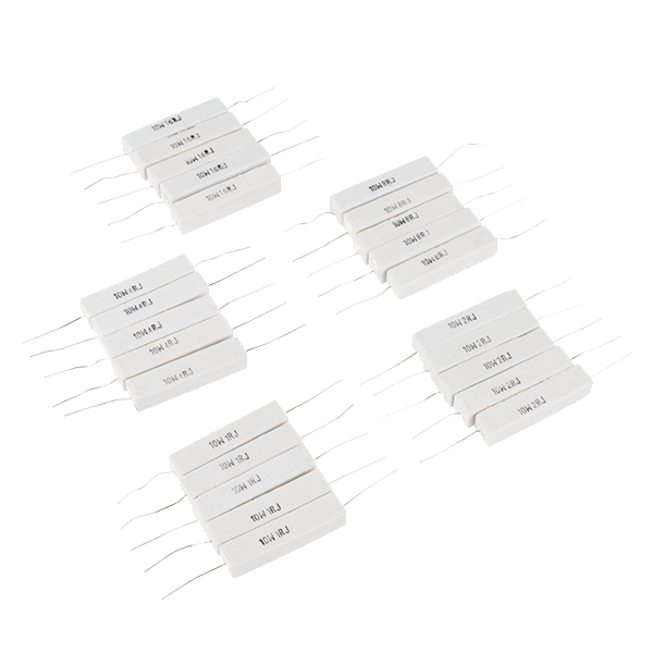
Then measure each cell's actual capacity, one at a time. Charge it to 4.20 V, rest it thirty minutes, then discharge through the power resistor at a steady current, timing until it reaches 3.00 V. Amp-hours is current times hours. It takes four sessions and it is the only way to know what you actually have: the number printed on the wrapper is a rating, not a measurement, and a cell that has been in a drawer for two years will not meet it.
Write the four capacities in your notebook as a table. That table is the input to step 3's arithmetic, and you will compare against it at the end of step 5.
If all four come out within a couple of per cent of each other, deliberately unbalance the string before going on: charge three of them fully and leave the fourth at about 60%. You need a visible effect to measure, and a well-matched string will not give you one in an afternoon.
One cell at a time on the charger. Never charge a series string without per-cell supervision — which is the whole point of this rung and the reason step 5 exists.
Tools needed:
 18650 Battery Holder 4-Cell
 Battery Holder
 LiPo Charger Board
 Digital Multimeter - Auto-Range, True RMS
 Power Resistor Kit - 10W (25 pack)
 Heat Sink Assortment (Aluminum)
 Stopwatch
 Battery Monitor (Coulomb Counter)
 Alligator Clip Test Leads
 Clear Safety Glasses
 Lab Notebook (Carbon Copy)
 18650 Lithium Cell
2
2
Discharge the string and watch the weakest cell end the job
Discharge the string and watch the weakest cell end the job
Wire the four-cell holder in series and bring a thin tap wire out of each cell junction, exactly as in rung 3 step 5. Those taps are how you watch individual cells while the string works.
Discharge the whole string through the power resistor at a steady current — an amp is plenty and keeps the resistor manageable. Every five minutes, read **all four cell voltages in turn** and the string total, and write them in a row.
Stop the moment **any single cell** reaches 3.00 V. Not the string; a cell. This is the point of the whole exercise: the string total will still look perfectly healthy — four cells averaging 3.4 V is a string at 13.6 V, which no total-voltage cut-off would object to — while one cell inside it is already at its floor and being dragged below.
Now look at your rows. The weak cell's voltage separates from the others early and then dives; the strong ones are still on their plateau when you stop. Work out how much charge the string delivered and compare it against the strongest cell's own capacity from step 1. The difference is capacity you own and cannot reach.
Over-discharging a lithium cell below about 2.5 V damages it permanently and makes it dangerous to recharge. Watching the cells rather than the total is not caution, it is the only correct way to run a string.
Tools needed:
18650 Battery Holder 4-CellPower Resistor Kit - 10W (25 pack)Heat Sink Assortment (Aluminum)Digital Multimeter - Auto-Range, True RMS MultimeterStopwatchAlligator Clip Test Leads
 Hookup WireClear Safety GlassesLab Notebook (Carbon Copy)
3
3
The arithmetic of drift
The arithmetic of drift
Loading Jupyter Notebook...
4
4
Build one balancing channel by hand
Build one balancing channel by hand
Before fitting a board that does it invisibly, build one channel so you can see what it does. A passive balancer is genuinely this simple.
Across one cell, put a **100 Ω resistor in series with a logic-level MOSFET**, drain to the cell's positive, source to the cell's negative. Drive the gate from a comparator that turns on whenever that cell exceeds the reference — 4.15 V is a sensible threshold, set with the potentiometer and checked against the meter. Use a 1 W or larger resistor: step 3 computed 0.18 W, and a quarter-watt part running at most of its rating in a closed pack is a bad idea.
Test it on the bench supply first, with no cell involved: sweep the supply up through the threshold and confirm the MOSFET turns on and the resistor starts drawing its 42 mA. Measure the current rather than assuming it; a MOSFET that is not fully on is a heater.
Now put it on the cell that runs high in your string and charge the string gently. That cell should stop climbing while the others catch up. You will feel the resistor get warm, and that warmth is the energy you are deliberately destroying — passive balancing does not move charge from a full cell to an empty one, it burns the difference.
Four of these, one per cell, is a complete passive balancer. Which is, very nearly, what is on the board in the next step.
Materials for this step:
Power Resistor Kit - 10W (25 pack)1 piece 1/4W Resistor Kit1 pieceHookup Wire1 piece
Tools needed:
 Breadboard
 Dupont Jumper Wire Set (M-F)
 IRLZ44N Logic-Level MOSFET
 LM393 Dual Comparator IC
 10K Ohm Linear Potentiometer
 Bench Power SupplyDigital Multimeter - Auto-Range, True RMS
 Infrared Thermometer
 Soldering Station
 Wire StrippersClear Safety Glasses
5
5
Fit a real BMS and measure what it bought you
Fit a real BMS and measure what it bought you
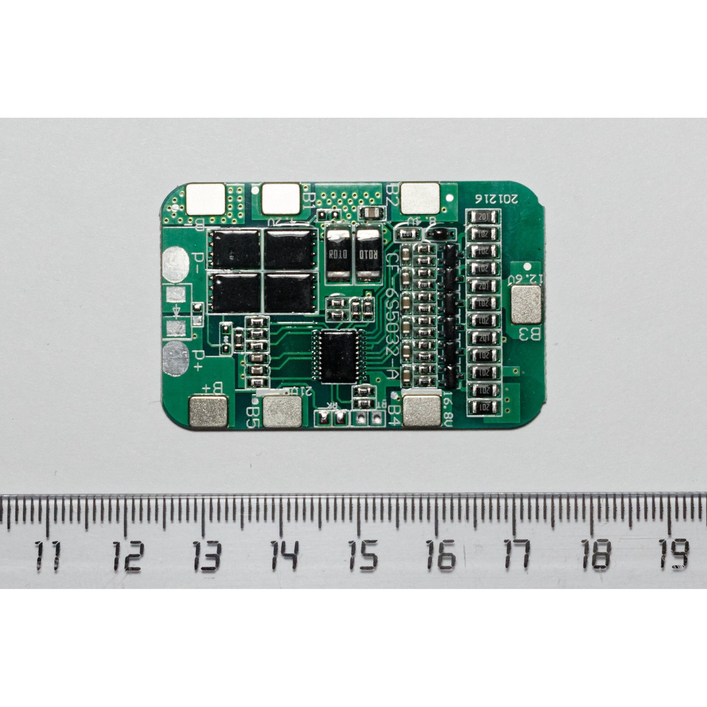
The green board in the photograph on this page is a 4S battery management system, and it is the commodity version of everything in steps 2 and 4. Its terminal strip takes **B−, then one wire per cell junction, then B+** — the same taps as the pack connector in rung 3.
Wire it carefully and in order, from B− upwards. Getting a balance lead onto the wrong junction reverses a cell input, and the board will not survive it. Measure each wire against B− with the meter before you plug the connector in, and confirm the voltages step up cell by cell. Do that check every time.
What the board is doing, in three jobs:
- **Overcharge protection** — it disconnects if any cell passes about 4.25 V.
- **Over-discharge protection** — it disconnects if any cell falls below about 2.5 V. This is the protection you were providing by hand with the meter in step 2.
- **Balancing** — the small resistors along one edge, doing what you built in step 4.
Charge the string with the board fitted and watch the four cell voltages converge over several hours. Put the infrared thermometer on the balance resistors while it works; they will be the warmest things on the board and that is correct.
Then repeat the step 2 discharge and compare the delivered amp-hours with the first run. That difference is the answer to the question this rung asks, measured on your own bench.
A BMS protects cells. It cannot repair them: a cell whose capacity has genuinely collapsed will still limit the pack, and no amount of balancing will change that. Replacing one cell in an old pack with a new one makes the mismatch worse, not better.
Materials for this step:
Hookup Wire1 pieceTools needed:
 BMS Board18650 Battery Holder 4-CellDigital Multimeter - Auto-Range, True RMSInfrared ThermometerLiPo Charger BoardPower Resistor Kit - 10W (25 pack)Heat Sink Assortment (Aluminum)Soldering Station
 Solder Wire
 Solder FluxWire Strippers
 Fine-Tip TweezersClear Safety GlassesLab Notebook (Carbon Copy)
6
6
History and context
History and context
**Attribution, stated honestly.** There is no single patent for cell balancing and none is asserted here. The problem is arithmetic — identical current, different capacity — and it was recognised as soon as anyone put cells in series, which is to say in 1800 with Volta's pile. What changed with lithium-ion is the *consequence*: a nickel cell that is overcharged vents and gets hot, while a lithium cell that is overcharged can do what rung 9 describes. Balancing stopped being an efficiency measure and became a safety requirement.
That is why the pack connector grew cell taps and why every lithium pack sold today has a protection board inside it, while a nickel-cadmium pack of the same era had nothing but cells and a thermistor.
**Passive against active.** Everything here is *passive* balancing: bleed the high cells down and waste the difference. *Active* balancers move charge from the high cell to the low one through an inductor or a transformer, so nothing is thrown away, and they are correspondingly more expensive and more complex. For a four-cell tool pack the passive version is right; for a car pack with a hundred cells in series it stops being right, because the energy you would throw away scales with the string.
**Honest limits.** Passive balancing is slow, as step 3 showed: 300 mAh of imbalance takes seven hours of bleeding. It only works at the top of the charge, where the voltage curve is steep enough to tell the cells apart — on the flat plateau of rung 4 a 50 mV difference could be almost any difference in state of charge. And it cannot fix a mismatch that is growing faster than it can bleed, which is what an ageing pack eventually becomes.
Materials
3- Power Resistor Kit - 10W (25 pack)10% commission1 piece$5.70
- 1 piecePlaceholder
- 2 piecesPlaceholder
Tools Required
27- Placeholder
- 14 vendors sell this, none ship to you yetPlaceholder
- LiPo Charger Board10% commissionPlaceholder
- Placeholder
- Power Resistor Kit - 10W (25 pack)10% commission$5.70
- Heat Sink Assortment (Aluminum)10% commissionPlaceholder
- Placeholder
- Battery Monitor (Coulomb Counter)10% commissionPlaceholder
- Placeholder
- Placeholder
- Lab Notebook (Carbon Copy)10% commissionPlaceholder
- 18650 Lithium Cell10% commissionPlaceholder
- Placeholder
- Placeholder
- 1 vendor sell this, none ship to you yetPlaceholder
- Placeholder
- Placeholder
- Placeholder
- Placeholder
- Placeholder
- Placeholder
- Placeholder
- Placeholder
- BMS Board10% commissionPlaceholder
- Placeholder
- Solder Flux10% commissionPlaceholder
- Placeholder
Estimated Total
What the maker bought. Materials shown without a price are sourced wherever you buy them.
Related Blueprints
These blueprints share knowledge with this one — techniques, materials, or principles that connect them in the learning graph.

One Can, Many Tools: The 18650 and the Safety Devices in Its Cap
by Volt
Electronics
39
0
0
0
0
0
The Pack as a Part: Contacts, Keying and the Third Wire
by Emma
Energy
31
0
0
0
0
0
Power: Why It Works on USB and Dies on a Battery
by Volt
Electronics
42
0
0
0
0
0
Knowing When To Stop: Finding the Peak That Says Full
by Volt
Electronics
34
0
0
0
0
0
CC0 Public Domain
This blueprint is released under CC0. You are free to copy, modify, distribute, and use this work for any purpose, without asking permission.
Support the Maker by purchasing products through their Blueprint where they earn a Maker Commission set by Vendors, or create a new iteration of this Blueprint and include it as a connection in your own Blueprint to share revenue.