ART
BEAUTY & WELLNESS
CRAFT
CULTURE & HISTORY
ENTERTAINMENT
ENVIRONMENT
FOOD & DRINKS
REVERSE ENGINEERING
SCIENCES
SPORTS
TECHNOLOGY
WEARABLES
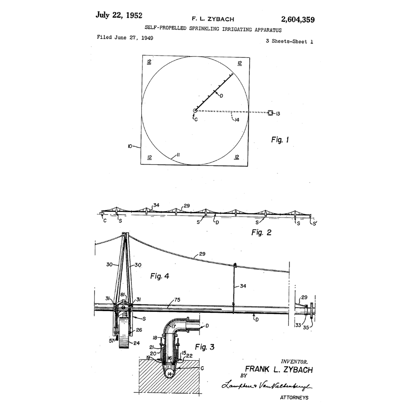


Centre-Pivot Irrigation: A Pipe That Walks Round the Well
Flood irrigation needs level land and wastes water; hand-moved sprinkler pipe needs labour every few hours. Frank L. Zybach of Strasburg, Colorado, anchored a sprinkler pipe at a well in the middle of the field and set it on wheeled towers about 200 feet apart, so it walked slowly round in a circle and watered the field without anyone moving it.
US 2,604,359, filed 27 June 1949 and granted 22 July 1952, drives each tower with the irrigation water itself: a cylinder fills, lifts a crank and ratchets the wheel forward, then empties through a larger outlet onto the crop beside the track. The outer tower sets the pace; a wire along the pipe at each other tower opens or closes its water as the pipe bows, keeping the line straight.
This rung works out the area, depth and nozzle sizing, models the alignment control, and builds a test pipe that puts more water out where the circle is bigger.
Intermediate
About 4 hours
Instructions
1
1
Area, depth, nozzle sizing and alignment
Area, depth, nozzle sizing and alignment
Loading Jupyter Notebook...
2
2
Lift the water from the well
Lift the water from the well
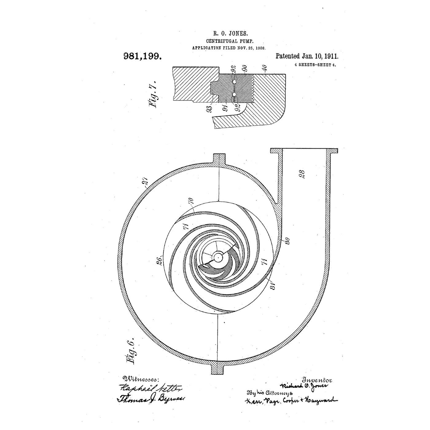
Zybach's machine needs pressure at the pivot: an artesian well if it has it, otherwise a pump. The embedded blueprint shows how a centrifugal pump makes that pressure.
3
3
Read the water drive on sheet 2
Read the water drive on sheet 2
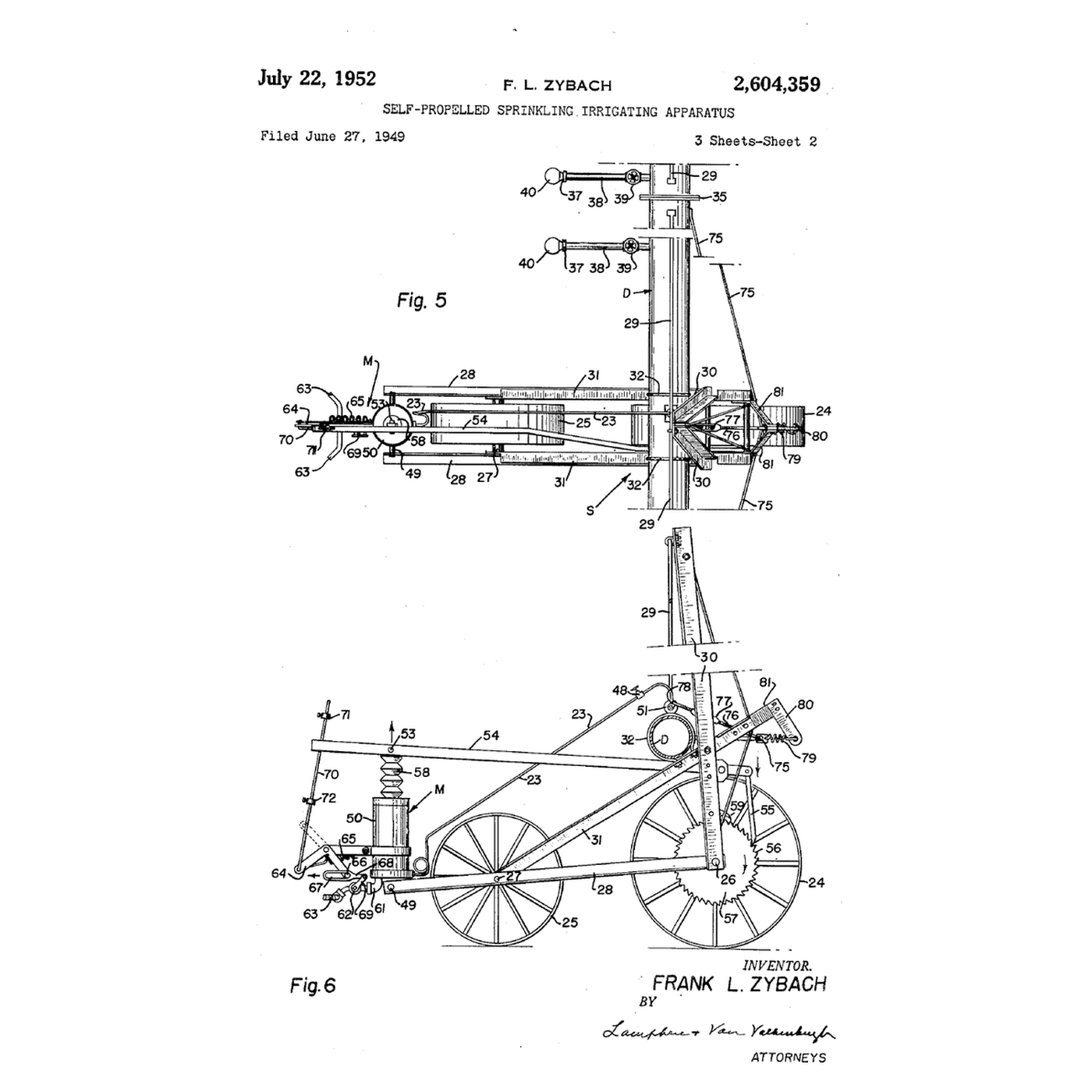
Fig. 6 shows one tower from the side. Water from the pipe comes down a small tube 23 through a regulating valve 51 into cylinder 50. The piston 52 rises slowly and its rod lifts crank 54; a ratchet 55 on the crank turns the toothed wheel 57 fixed to drive wheel 24, and pawl 59 stops it turning back.
At the top of the stroke the crank lifts stop 71 on rod 70, flips a spring toggle 64 over centre and opens valve 62 on the large outlet 61: the cylinder drains faster than the small tube can fill it, and the piston falls. At the bottom, stop 72 flips the toggle back and closes the outlet. The outlet spouts 63 point to each side of the wheel track, so the drive water lands on the crop, not in the rut.
Fig. 5, above it, shows the alignment wire 75 fixed to the pipe on each side of the tower, running to the regulating valve. The patent makes it of Invar, whose tiny thermal expansion stops the sun from upsetting the alignment.
4
4
One tower's drive stroke
One tower's drive stroke
Blockly Workspace
Loading Blockly workspace...
5
5
Build a test pipe that grows its flow with radius
Build a test pipe that grows its flow with radius
Cap one end of a 1.2 m length of 20 mm PVC pipe and connect the other end to a garden hose through a ball valve and pressure gauge. Lay it level on two stands over a line of cups, one under each hole. Call the hose end the pivot.
**Equal holes.** Drill 1.5 mm holes every 100 mm. Open the valve to a steady low pressure and collect for one minute. Measure each cup in a graduated cylinder: the flows are nearly equal. Divide each by the ring area its hole must water, $2\pi r \times 0.1$ m, and the depth falls steeply with radius.
**Zybach's rule.** On a second pipe, drill 14 of the same holes spaced closer together towards the far end, so that each waters an equal share of the circle: hole $k$ at $r = 1.2\,\text{m} \times \sqrt{(k - \tfrac12)/14}$, which is 227, 393, 507, 600, 680, 752, 818, 878, 935, 989, 1039, 1088, 1134 and 1178 mm. Repeat the test. Now the flow per metre of pipe grows with radius. Work out the depth each hole delivers to its own ring: it should be nearly flat.
Materials for this step:
 PVC Pipe3 meters
 PVC Pipe Fittings Assortment1 piece
 Brass Ball Valve1 piece
 PTFE Thread Seal Tape1 piece
 Sprinkler Head1 piece
 Water20 liters
Tools needed:
 Pressure Gauge
 Cups
Cups Graduated Cylinder
 Stopwatch
 Tape Measure
 Cordless Drill
 Drill Bit Set
 Permanent Marker
 Garden Hose
6
6
Keeping the towers in line
Keeping the towers in line
The alignment control in the patent, as a decision each tower makes continuously.
Flow
Loading...
7
7
History and context
History and context
**Frank L. Zybach** of Strasburg, Colorado, filed **US 2,604,359**, *Self-Propelled Sprinkling Irrigating Apparatus*, on 27 June 1949; it was granted 22 July 1952. The design was taken into production in Nebraska in the 1950s, and later machines replaced the water drive with an electric motor at each tower while keeping the master-tower-and-alignment idea.
Pivot circles are the green discs seen from the air over dry farmland across the world.
**Honest limits.** A circle leaves the corners of a square field dry unless a corner arm or separate watering is added, as the patent itself says. The outer spans must put water down fast, which can run off on heavy soils. And pivots draw heavily on groundwater: in parts of the High Plains the aquifer has fallen far faster than it refills.
Materials
6- 3 metersPlaceholder
- 1 piecePlaceholder
- 1 piecePlaceholder
- 1 piecePlaceholder
- Sprinkler Head10% commission1 piecePlaceholder
- 20 litersPlaceholder
Tools Required
9- Placeholder
- Placeholder
- Placeholder
- Placeholder
- 1 vendor sell this, none ship to you yetPlaceholder
- 1 vendor sell this, none ship to you yetPlaceholder
- Placeholder
- Placeholder
- Garden Hose10% commissionPlaceholder
Related Blueprints
These blueprints share knowledge with this one — techniques, materials, or principles that connect them in the learning graph.

CC0 Public Domain
This blueprint is released under CC0. You are free to copy, modify, distribute, and use this work for any purpose, without asking permission.
Support the Maker by purchasing products through their Blueprint where they earn a Maker Commission set by Vendors, or create a new iteration of this Blueprint and include it as a connection in your own Blueprint to share revenue.