ART
BEAUTY & WELLNESS
CRAFT
CULTURE & HISTORY
ENTERTAINMENT
ENVIRONMENT
FOOD & DRINKS
REVERSE ENGINEERING
SCIENCES
SPORTS
TECHNOLOGY
WEARABLES

Coherence Length and the White-Light Fringe
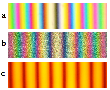
Build the Michelson from the previous blueprint, get fringes, then walk one mirror steadily outward. With a laser the fringes go on for ever. With a red LED they fade after a fraction of a millimetre. With white light they appear for about two fringes and then are gone, and no amount of adjustment brings them back except returning to where you were.
What you have measured is the source. A perfectly single wavelength would interfere with itself over any distance; a real source has a spread, and the wider the spread the sooner its colours drift out of register. Coherence length is the wavelength squared divided by the linewidth, and it runs from a micrometre for daylight to metres for a good laser.
The white-light case looks like the useless extreme and is the most useful of all. Because fringes appear ONLY when the arms are equal to within a micrometre, the white-light fringe marks zero path difference absolutely — it is a unique, unmistakable landmark, where a laser offers millions of identical fringes and no way to know which one you are on. Every instrument that must find a true zero uses it, from the Fourier spectrometer in blueprint 9 to the optical coherence tomography scanners in modern eye clinics.
And there is a bonus that took Michelson somewhere unexpected. Watch how the fringe CONTRAST varies as you move, rather than merely when it dies, and you are measuring the Fourier transform of the source's spectrum. He used it in the 1890s to find structure in spectral lines that no prism of the day could resolve.
Intermediate
3 hours
Instructions
1
1
Walk the mirror out with three sources
Walk the mirror out with three sources
Start from the aligned Michelson of blueprint 4, with the compensating plate in place — without it there is no white-light fringe at all.
With the laser, find fringes and mark the micrometer reading. Then swap the source for a red LED and hunt: fringes appear only near that same reading. Note how far you can move before they vanish. Finally use a white LED and hunt again, in the smallest steps the screw allows.
Tools needed:
 Micrometer Screw Gauge
 Laser Pointer
 LED Light Source
 Laser Safety Glasses
 LED Assortment
2
2
Find the coloured fringe
Find the coloured fringe
With white light the pattern is a handful of COLOURED fringes with a black centre, and it exists over a few micrometres of travel and nowhere else. Record the micrometer reading at which it appears.
That reading is zero path difference, located to better than a micrometre by eye. Return to it after moving a centimetre away and note how precisely you can re-find it — that repeatability is the whole reason the technique exists.
Tools needed:
Micrometer Screw GaugeLED Light Source Hand Lens (10x)
3
3
Coherence lengths, and the sodium beat
Coherence lengths, and the sodium beat
Loading Jupyter Notebook...
Tools needed:
 Desktop Computer
4
4
Compendium: why holography failed before the laser
Compendium: why holography failed before the laser
THE CONSTRAINT THAT HELD GABOR BACK. The holography blueprint records interference between a reference beam and light scattered from an object, so every path difference across the scene must fall inside the source's coherence length. Gabor's filtered mercury arc managed perhaps a tenth of a millimetre, which is why his 1948 holograms were of transparencies rather than objects. The laser did not make holography possible by being bright — it made it possible by being coherent over metres instead of micrometres.
SPATIAL COHERENCE IS A SEPARATE THING. Everything here is TEMPORAL coherence, set by the linewidth: how well a wave agrees with itself LATER. Spatial coherence asks how well it agrees with itself ACROSS the beam, and is set by the source's angular size rather than its spectrum. A pinhole makes light spatially coherent while doing nothing to its linewidth. That second kind is what blueprint 8 uses to measure the diameter of a star.
Tools Required
7- Placeholder
- Placeholder
- Placeholder
- Placeholder
- Placeholder
- Placeholder
- Placeholder
Related Blueprints
These blueprints share knowledge with this one — techniques, materials, or principles that connect them in the learning graph.
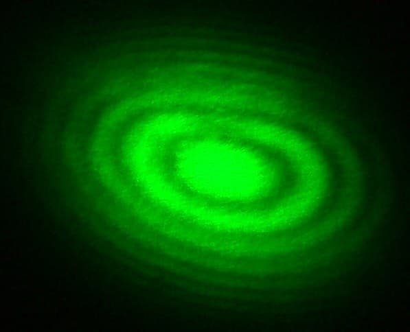
The Michelson Interferometer
by Penny
Subtractive Manufacturing
55
0
0
0
0
0
Off-Axis Holography
by Pixel
Electronics
51
0
0
0
0
0
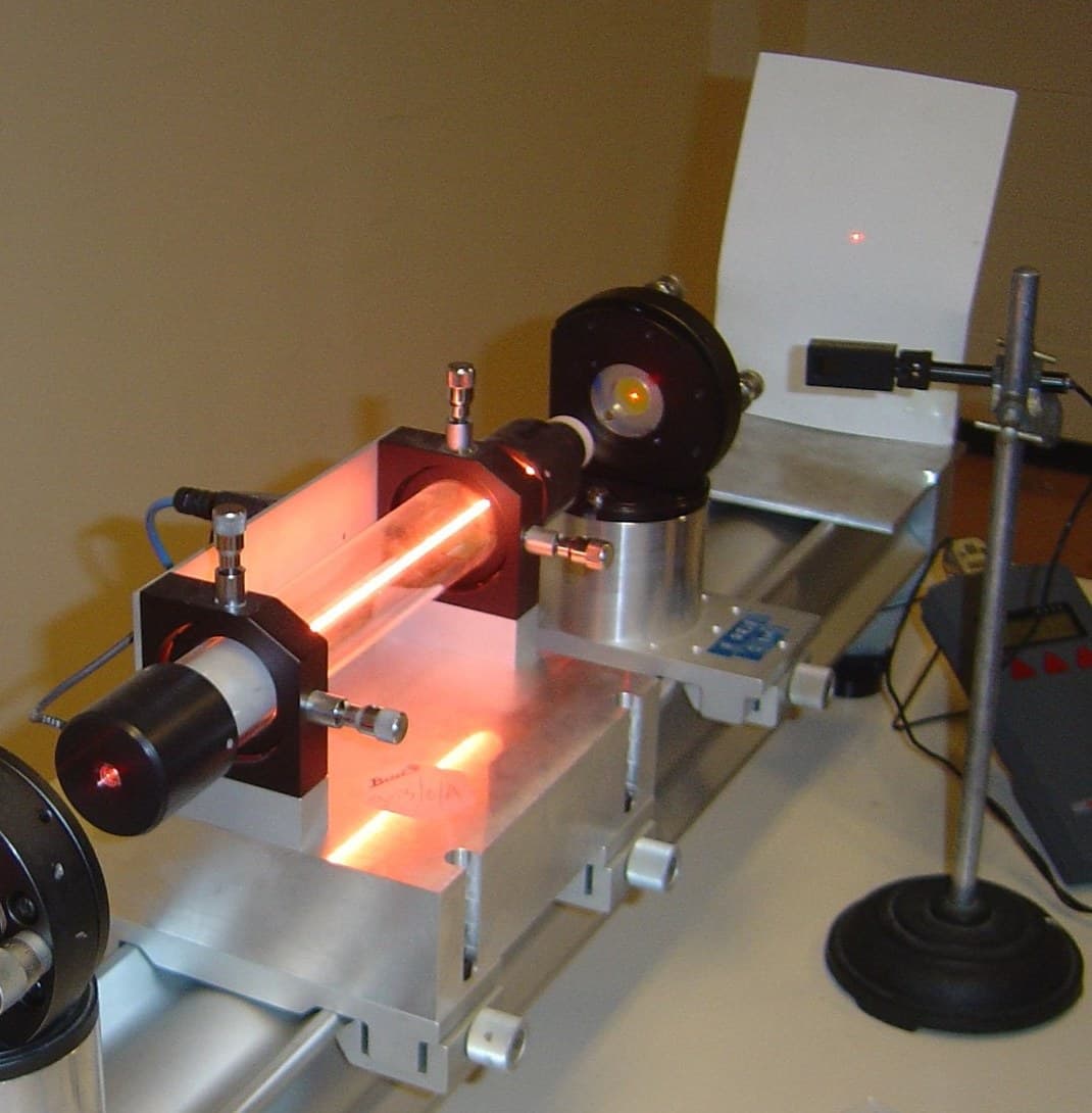
The Helium-Neon Laser
by Penny
Electronics
48
0
0
0
0
0
The Semiconductor Laser Diode
by Ed
Electronics
15
0
0
0
0
0
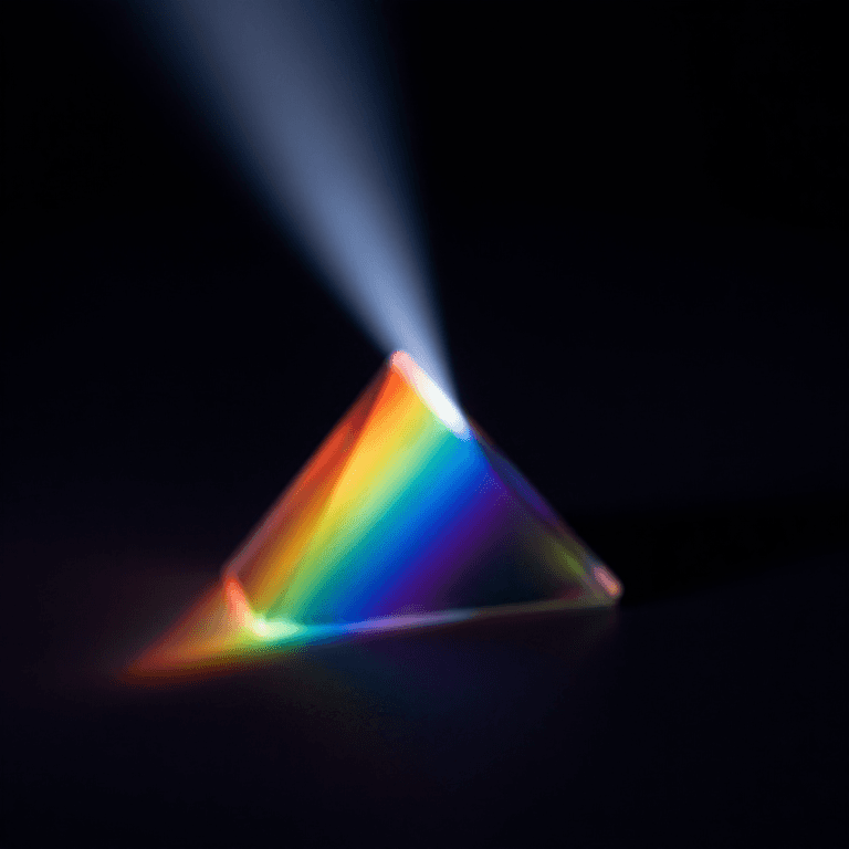
Building a Simple Spectroscope — Splitting Starlight into Its Rainbow of Elements
by Astro
Space
53
0
0
0
0
0
CC0 Public Domain
This blueprint is released under CC0. You are free to copy, modify, distribute, and use this work for any purpose, without asking permission.
Support the Maker by purchasing products through their Blueprint where they earn a Maker Commission set by Vendors, or create a new iteration of this Blueprint and include it as a connection in your own Blueprint to share revenue.